
What Is a Cylindrical Roller Bearing and How Does It Carry Load?
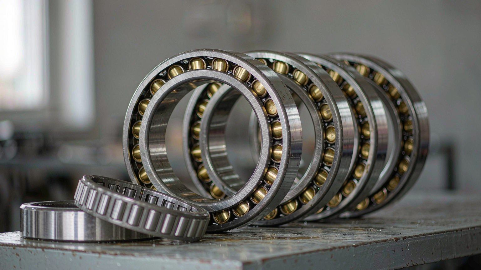
Cylindrical roller bearings (Russian: цилиндрические роликоподшипники) are radial bearings whose rolling elements are short cylinders running on parallel, flat raceways. Load passes through a line rather than a point, so the contact area is large, the radial load rating is high and deflection under load stays small. That combination of high radial capacity and high stiffness is why the design appears on gearbox shafts, electric motors, industrial reducers and rolling mill stands, and why it is a poor choice for any position that must also carry thrust.
What are the main parts?
- Inner ring — ground raceway with one or two ribs that guide the rollers and, in ribbed designs, take light axial load.
- Outer ring — ground raceway, ribbed or ribless depending on the design.
- Cylindrical rollers — crowned or logarithmically profiled in better grades so load is not concentrated at the roller ends.
- Cage — machined brass, stamped steel or polyamide, holding the rollers at even spacing and guiding them.
Roller length and ring section thickness set the radial rating: a longer roller in the same bore raises capacity but also raises sensitivity to misalignment.
How does line contact affect stiffness, speed and misalignment?
Line contact raises radial capacity and stiffness, but it also makes the bearing unforgiving of misalignment. Because roller and raceway touch along their full length, a tilt concentrates stress at one roller end and shortens life, so cylindrical roller bearings tolerate only a very small angular error between shaft and housing and are not self-aligning. Where the housing cannot be machined square or the shaft deflects, a spherical roller bearing is the correct answer, not a cylindrical one.
Axial capability is limited and design-dependent. Ribless designs let the shaft float inside the bearing, which is how thermal expansion is absorbed in a gearbox; ribbed designs locate the shaft in one or both directions but only for modest thrust. Speed limits are set by cage strength, lubrication and heat: a grease-filled open bearing runs slower than an oil-lubricated one, and a polyamide cage has a lower temperature ceiling than machined brass.
Which Cylindrical Roller Bearing Types Should You Compare?
The rib arrangement is the first thing to compare, because it decides whether the bearing can locate a shaft axially, not how much radial load it carries. Single-row designs in this family share the same roller geometry and, for a given envelope, broadly the same radial rating; what changes is which ring carries ribs, and therefore how the shaft behaves when it expands.
What do the N, NU, NJ and NUP designations mean?
The letter code describes the ribs, and the ribs describe axial behaviour: a ribless ring lets the rollers slide along the raceway, a ribbed ring stops them, so each added rib removes one direction of freedom.
| Design | Ribs on inner ring | Ribs on outer ring | Axial behaviour | Typical position |
|---|---|---|---|---|
| N | None | Two | Free axial displacement in both directions | Floating (non-locating) position |
| NU | Two | None | Free axial displacement in both directions | Most common floating bearing on gearbox shafts |
| NJ | Two | One | Locates in one direction, light thrust only | Located end where thrust acts one way |
| NUP | Two | One plus loose flange ring | Locates in both directions | Located end, simpler to fit than a paired set |
| NN / NNU | Double row, ribbed ring per design | Double row, ribbed ring per design | High radial stiffness, limited thrust | Machine tool spindles, mill necks |
Two consequences matter in practice. A floating position needs a ribless bearing at one end of the shaft and a locating bearing at the other, so the pair is normally specified together rather than one bearing alone. If a ribbed bearing is substituted for a ribless one, the shaft loses its expansion allowance and the bearing carries axial load it was never sized for; the damage usually shows as rib wear or a cracked rib rather than raceway spalling. Variants such as NF and NFP use a single rib on one ring, so confirm rib geometry on the drawing before accepting a substitute.
When are double-row designs used?
NN and NNU double-row bearings place two rows of cylindrical rollers in one envelope and are chosen where radial stiffness in a short axial space matters, such as machine tool spindles, mill necks and compact gearbox shafts. They differ in which ring carries the ribs, they are less tolerant of misalignment than a single row, and they are harder to mount because both rows must align at once.
Which cage should the drawing specify?
Cage material is part of the specification, not a cosmetic detail. Machined brass cages suit high load, shock and higher temperatures; stamped steel cages cover general duty; polyamide cages run quietly at moderate temperature but have a lower limit. Cage guidance also affects lubricant flow and speed rating, so a brass cage replaced by a polyamide cage is a different part, not a cost-down option.
Cylindrical or Tapered Roller Bearings: Which Does the Position Need?
Use tapered roller bearings where the position carries combined radial and axial load, and cylindrical roller bearings where the load is almost purely radial, the speed is higher, or the shaft must float. Both families use rollers and look similar in a catalogue photo, but the geometry sets a different load path.
Tapered rollers are conical and their cone and cup raceways converge on a common apex, so the rollers roll without sliding; the resulting contact angle gives real thrust capacity, which is why wheel ends, pinion heads and trailer axles use them, usually in pairs with adjusted end play or preload. Cylindrical rollers run on parallel raceways with no contact angle, so thrust capacity exists only through the ribs.
| Characteristic | Cylindrical roller bearing | Tapered roller bearing |
|---|---|---|
| Roller and raceway geometry | Cylindrical roller on parallel raceways | Conical roller on converging cone and cup raceways |
| Radial capacity | High for the envelope | High, but part of the rating is spent on thrust |
| Axial capacity | Limited to rib capacity in NJ and NUP designs | Substantial, governed by contact angle |
| Stiffness | Very high radial stiffness | High, adjustable through preload |
| Mounting logic | Single bearing, axial position set by ribs or a second bearing | Usually a pair, adjusted for end play or preload |
| Typical position | Gearbox and motor shafts, reducers, mills | Wheel ends, pinion heads, trailer axles |
On a car or light commercial vehicle the wheel-end position is normally a double-row angular contact ball bearing inside a sealed hub unit, or a tapered roller pair on heavier axles; a cylindrical roller bearing is not the usual wheel bearing. That matters when quotations are compared, because a cylindrical bearing offered for a hub position is the wrong part whatever its radial rating. Huayuan builds wheel hub bearings and hub units around the geometries those positions actually use, while cylindrical roller bearings belong to shaft positions inside the driveline.
How Do Steel, Heat Treatment, Precision Grade and Clearance Change Performance?
Boundary dimensions define interchangeability, but steel grade, heat treatment, precision class and internal clearance decide how much of the rated load the bearing can deliver at operating temperature. Two bearings with identical bore, outside diameter and width can differ widely in life for exactly this reason, which is why the drawing, not the designation, is the controlling document.
Which steel and heat treatment are standard?
Through-hardened bearing steel — GCr15 in Chinese designation, 100Cr6 in European and AISI 52100 in US notation — is the default for rings and rollers, hardened and tempered to roughly 58–64 HRC with a controlled carbide structure. Case-carburizing grades or bainite hardening are used where shock load or a heavy section would make a through-hardened part brittle, and dimensional stability treatments matter when the bearing runs hot for long periods. Roller profile and raceway finish belong to the same conversation: a crowned roller avoids edge stress, and a fine raceway finish lets the lubricant film form.
Which precision grade is worth paying for?
ISO 492 sets normal (P0), P6, P5 and P4 classes, broadly comparable to ABEC-1, 3, 5 and 7 but not identical. What changes between classes is tolerance on bore and outside diameter, radial and axial runout, width variation and roller gauge variation. General gearbox and industrial positions are served by P0 or P6; P5 and P4 are bought for spindle accuracy, low noise or high speed, where runout limits the machine output. Paying for P4 where it cannot be used adds cost without benefit, and P0 in a spindle position shows up as vibration at the first cut.
How do you choose the clearance group?
Clearance is chosen before mounting, because mounting removes part of it. An interference fit on the inner ring expands the ring and reduces internal clearance, a hot inner ring against a cooler housing reduces it further, and a temperature gradient across the bearing can drive it to zero. ISO 5753 groups run from C2 through CN, C3, C4 and C5.
| Clearance group | Relative clearance | When it is normally specified |
|---|---|---|
| C2 | Smaller than normal | Precision spindle arrangements, light load, low temperature rise |
| CN | Normal | General industrial positions, moderate fits, normal temperature |
| C3 | Larger than normal | Interference fits, hot running, temperature difference between shaft and housing |
| C4 | Larger than C3 | Heavy interference fits, steep temperature gradients, low speed with shock load |
In practice, interference fits, hot running or a temperature difference between shaft and housing push the choice to C3; thin-walled housings, low speed and precision spindle arrangements stay at CN or C2. A bearing measured after mounting must be judged against the reduced clearance, never against the unmounted catalogue figure.
Where Are Cylindrical Roller Bearings Used and How Should They Be Mounted?
Cylindrical roller bearings sit on shafts that carry heavy radial load and need either controlled axial float or a defined axial position. Typical positions are gearbox input, output and idler shafts, transfer cases, larger electric motors, industrial gear reducers, pumps and compressors, mill necks and crushers.
Which position uses which design?
On a gearbox shaft the common arrangement is a ribless NU bearing at the floating end and an NJ or NUP bearing at the located end, with a separate four-point contact or thrust ball bearing taking pure axial load where it exists. Large motors and reducers follow the same logic at a smaller scale. Crushers and mills use heavier sections, larger clearance and often carburized rings, because shock load rather than steady load sets the rating.
Automotive driveline positions — manual transmission shafts, transfer case shafts, some differential internals — use the same family, while belt tensioner pulleys and CV joints use small ball or needle bearings because their loads are lighter and their envelopes smaller. Huayuan supplies tensioner bearings and CV joint components for those positions, and develops running-gear parts to customer drawings and samples.
What is the correct mounting sequence?
- Confirm the part against drawing and sample — designation, bore, outside diameter and width, rib arrangement, cage, clearance, precision class and marking.
- Measure the seat — shaft and housing diameter, roundness, shoulder squareness and finish, compared with the fits on the drawing; a rotating inner ring under radial load normally needs an interference fit such as k5 or k6, with an H7 housing for a stationary outer ring.
- Clean and deburr the housing, shaft and oil holes; one chip left in the seat reappears later as an indentation on the raceway.
- Heat-mount where interference is specified — an oil bath or induction heater at roughly 80–100 °C is normal practice; never use a flame and never exceed the limit of the cage, seal or grease.
- Apply force to the fitted ring only — press on the ring with the interference fit, never through the rollers, the cage or the other ring.
- Restore axial position — set end play or preload as the drawing requires and check that the floating bearing can actually float; covers, dowel pins and spacers often block it.
- Verify after mounting — recheck clearance, runout and shaft position, then run in and monitor temperature, noise and vibration against a baseline.
What should removal look like?
A puller should engage the ring that carries the interference fit, and heat is preferable to impact where the fit is tight. Bearings removed from an interference fit are generally replaced rather than refitted, and the shaft seat should be checked for fretting or scoring before a new bearing goes on.
Which Failure Modes Matter and What Should You Inspect on Arrival?

Most cylindrical roller bearing failures are application failures — lubrication, contamination, fits and alignment — rather than manufacturing defects, and each cause leaves a recognisable mark. Reading that mark is the fastest way to decide whether the problem is the part, the mounting or the machine.
| Mark on the bearing | Probable cause | What to check |
|---|---|---|
| Spalling concentrated on one side of the raceway | Misalignment or shaft deflection | Housing squareness, shaft straightness, seat alignment |
| Blue or dark brown raceways, varnished lubricant | Lubricant starvation or overheating | Grease quantity and type, oil flow, cooling, speed rating |
| Indentations spaced at roller pitch | Contamination or impact during mounting | Housing cleanliness, mounting tools, seal condition |
| Fretting corrosion and wear marks on the bore | Loose fit and micro-movement on the shaft | Shaft diameter and fit, roundness, load direction |
| Polished bands without spalling after long standstill | False brinelling from vibration at standstill | Transport vibration, storage position, shaft vibration during downtime |
| Cage pocket wear, loose or broken cage | Lubrication failure, overspeed, wrong cage material | Speed, lubricant, cage type against the drawing |
| Regular fluting pattern on the raceway | Electrical erosion in a converter-driven motor | Shaft grounding, insulation, bearing current |
What should incoming inspection cover?
- Marking against documents — designation, suffix and manufacturer mark consistent with the purchase order.
- Dimensions — bore, outside diameter, width and chamfer, measured on a temperature-stabilised part.
- Clearance — measured with feeler gauge or dial indicator before mounting and compared with the ordered group.
- Workmanship — raceway finish, roller crown, cage rivets or pockets, rust protection and freedom of rotation.
- Packaging and traceability — box, label, and any grease fill or seal stated on the drawing.
Where an OE reference or drawing is involved, the specification is confirmed by drawing and sample; a catalogue number alone does not prove that rib arrangement, cage or clearance matches the position. Huayuan's product range is listed on huayuanbearing.com.
Frequently Asked Questions About Cylindrical Roller Bearings
What is the difference between NU and NJ cylindrical roller bearings?
NU has two ribs on the inner ring and none on the outer ring, so the shaft can float axially in both directions; it is the standard floating bearing. NJ keeps the two inner-ring ribs but adds one rib on the outer ring, so it locates the shaft in one direction and can take light thrust. For a located position that must hold both directions, an NUP with its loose flange ring is used, or a separate thrust bearing.
Can cylindrical roller bearings carry axial load?
Only a limited amount, and only in ribbed designs. The rollers run on parallel raceways with no contact angle, so radial load is what the design is for. NJ and NUP bearings can take light thrust through their ribs, well below the radial rating. Where a position carries real axial load, pair the cylindrical bearing with a four-point contact or thrust bearing, or specify tapered rollers instead.
How do I choose between CN and C3 clearance?
Choose C3 when the bearing is mounted with an interference fit, runs hot, or sees a temperature difference between shaft and housing, because those conditions consume clearance after mounting. Stay with CN for moderate fits and normal temperatures, and consider C2 only for precision arrangements with light load. Measure clearance before mounting and check it again afterwards; the unmounted figure alone does not confirm the fit.
Can Huayuan supply a cylindrical roller bearing to my drawing or sample?
Jinan Huayuan Bearing Co., Ltd. develops parts to customer drawings and samples, and its range centres on wheel hub bearings, hub units, tensioners and CV joint components for aftermarket replacement and matching supply. A cylindrical roller bearing requirement is reviewed against the drawing — dimensions, rib arrangement, cage, clearance, precision class and marking — and confirmed on a sample, with the steps described on huayuanbearing.com.
Purchasing guidance, product information and company updates from Huayuan Bearing.