
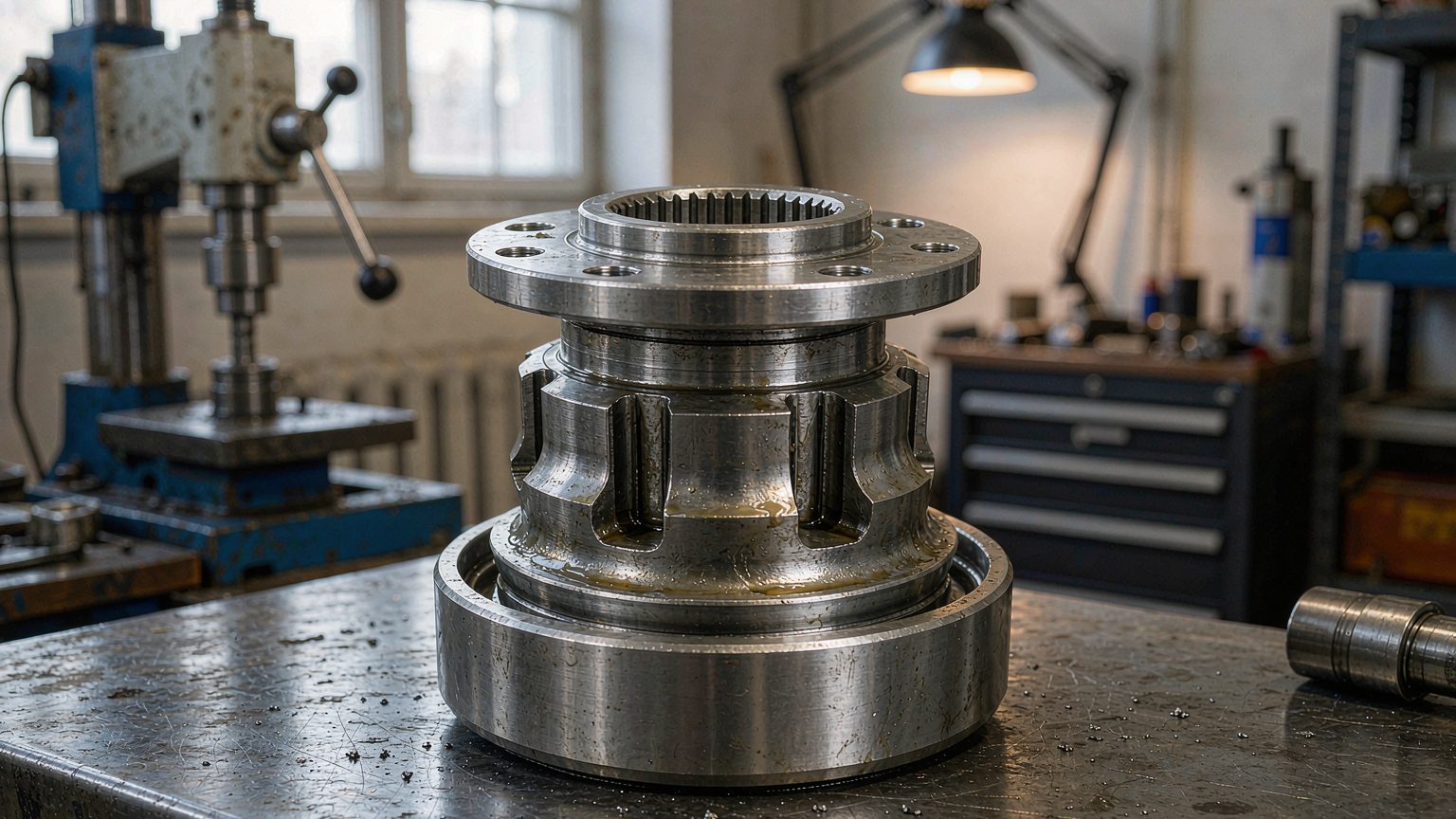
What Is a Hub Bearing and What Does Its Structure Actually Do?
A hub bearing is a sealed, pre-greased rolling bearing that connects a rotating wheel hub to the stationary suspension, and its structure is arranged to carry radial and axial load at the same time while keeping grease in and water out.
Every force generated at the tyre contact patch — vehicle weight, cornering force, braking torque reaction and kerb impact — passes through one of these joints at each corner of the vehicle. That is why the internal layout is almost never a single row: it is a double-row angular contact ball bearing, a double-row tapered roller bearing, or a pair of opposed single-row tapered bearings adjusted against each other on older light-truck axles.
Jinan Huayuan Bearing Co., Ltd. (huayuanbearing.com) manufactures wheel hub bearings, hub units, tensioner pulleys and CV joints in Jinan, Shandong, for aftermarket and OE programmes; the notes below are written so that an importer or workshop buyer can read a specification instead of a catalogue photo.
Where the load path runs on a driven and a non-driven corner
The load path starts at the wheel bolts and ends at the knuckle or axle housing, and every structural choice inside the bearing is a compromise between stiffness, friction and sealing.
On a non-driven corner the bearing sits between the steering knuckle or axle beam and the hub flange that carries the brake disc and road wheel. On a driven corner the inner ring is splined to the outer race of the constant velocity joint, so the same bearing also reacts drive torque and the plunge forces of the shaft. Four loads have to be handled: radial load from vehicle weight, axial load from cornering, torque reaction under braking and acceleration, and shock load from potholes and kerbs.
The components inside the assembly
Six functional groups make up a modern hub bearing, and a weak link in any one of them shortens the life of the whole unit.
- Outer ring — one or two raceways, fixed to the knuckle or axle housing, sometimes with an integral mounting flange.
- Inner ring or rings — rotate with the hub or drive shaft; on third-generation units the inner ring is flanged and splined.
- Rolling elements and cage — balls or tapered rollers, separated and guided so that they do not skew under load.
- Seals — usually a cassette or labyrinth design with an elastomer lip; seal damage, not raceway fatigue, is the most common root cause of premature replacement.
- Grease — a life-time fill matched to the seal material and to the running temperature of that corner.
- Encoder ring — a magnetic ring on the sealed side that lets the ABS sensor read wheel speed without a separate toothed ring.
What Are the Differences Between First-, Second- and Third-Generation Hub Units?

The three generations differ in how much of the corner is built into the bearing: a first-generation unit is a bearing only, a second-generation unit adds a flange to the outer ring, and a third-generation unit is a complete bolt-on hub module.
The label describes the mounting interface, not the quality level. A well-made first-generation bearing can outlast a poorly made third-generation unit, so a buyer should read the generation as a description of what has to be replaced on the vehicle, not as a ranking of durability.
| Feature | Generation 1 | Generation 2 | Generation 3 |
|---|---|---|---|
| Structure | Double-row bearing, no flange | Double-row bearing with flanged outer ring | Complete hub module with flanged inner and outer rings |
| Fixing to the vehicle | Pressed into knuckle or hub, retained by snap ring or nut | Bolted to the knuckle through the outer flange | Bolted to the knuckle; wheel and brake disc mount on the inner flange |
| Drive shaft interface | Separate hub or shaft | Separate hub shaft pressed in | Splined bore with axle nut |
| ABS provision | Usually none | Optional encoder ring | Encoder ring normally integrated |
| Preload | Set during installation or by clamped inner rings | Set at assembly | Set and sealed at the factory |
| What the workshop replaces | Bearing only | Bearing and flange, hub reused | Whole hub assembly |
Generation 1: the bearing alone
A first-generation hub bearing is a self-contained double-row bearing that depends on the surrounding parts to hold it together and to set its preload.
It remains common on rear axles, trailers and older passenger cars, and it demands the most skill at installation because press-fit depth, clamp load and nut adjustment all influence the internal preload. Buyers ordering this type should expect to discuss the intended vehicle position, because the same bore and width can carry different internal clearance depending on how the axle locates the rings. The range is listed on our wheel hub bearings page.
Generation 2: a flange on the outer ring
A second-generation unit adds a flange to the outer ring so that the bearing bolts directly to the knuckle instead of being pressed into it.
This removes the knuckle press-fit, which shortens labour time and removes one common installation error, a bearing driven in at an angle. The hub shaft is still a separate part, so the inner ring interface and the shaft shoulder must be in good condition before a new unit goes on; a worn shoulder transfers load into the seal and shortens life. Second-generation units are widely used on rear axles and on light commercial vehicles.
Generation 3: the complete corner module
A third-generation hub unit combines bearing, hub flange, wheel bolt circle and usually the ABS encoder into one sealed part that is fitted as a single item.
Because preload, grease fill, seal and encoder are set once at the factory, the workshop only bolts the unit to the knuckle and torques the axle nut to the figure in the manual. The trade-off is economic rather than technical: the whole module is replaced even when only one element has worn. Some catalogues use intermediate labels, for example a 2.5 designation for a unit flanged on the inner ring; those labels are commercial conventions and should always be checked against the drawing. Our hub units range is developed from drawings and samples for exactly this reason.
Tapered Roller or Ball: Which Rolling Element Suits the Corner?
Choose tapered rollers when the corner must be stiff and carries high combined load, angular contact balls when friction and mass matter more, and cylindrical rollers only where the load is essentially radial.
| Property | Tapered roller | Angular contact ball | Cylindrical roller |
|---|---|---|---|
| Radial capacity | High | Moderate | Very high |
| Axial capacity | High, one direction per row | Moderate to high, depending on contact angle | None |
| Stiffness under cornering | High | Moderate | High radially, none axially |
| Friction and heat | Higher | Low | Low to moderate |
| Typical position | Light truck, SUV and older driven hubs; trailer axles | Passenger car hub units of all three generations | Heavy radial locations where axial location comes from another part |
| Setting requirement | Preload or end play must be defined | Preload set by ring geometry | Normally clearance, no preload |
Tapered roller geometry and why preload matters
A tapered roller bearing carries combined radial and axial load because its rollers and raceways are conical and their apexes converge on the shaft axis, so the rollers roll rather than skid.
The setting is critical. Too little preload lets the roller/raceway contact slip under light load and smear the surface; too much raises running temperature, reduces grease life and can seize a unit on a long descent. On first-generation truck hubs the setting is made with an adjusting nut; on sealed hub units it is fixed by the geometry of the rings, which is why a sealed unit cannot be re-shimmed. Buyers should ask for the clearance or preload value on the drawing rather than inferring it from the part number.
Angular contact ball and cylindrical roller alternatives
Angular contact ball bearings dominate passenger-car third-generation units because low friction and low mass matter more than ultimate load capacity at that size.
Their contact angle determines how much axial load the row can take, and in a double-row arrangement the two rows face each other so that the pair accepts axial load in both directions. Cylindrical roller bearings carry very high radial load with no axial capacity at all, so they appear only where axial location is provided by another element of the assembly.
How Are Tensioner Pulleys and CV Joints Structured Differently?
A tensioner pulley is a bearing with a wheel moulded or stamped around it, while a ball-type CV joint is a four-part mechanism — inner race, cage, balls and outer race — that transmits torque at constant velocity through a steering angle.
Tensioner pulley structure
A tensioner pulley is a deep groove ball bearing fitted with a polymer or steel pulley shell, a dust shield and usually an offset or shoulder that locates it on the tensioner arm.
The dominant load is radial, coming from belt tension, and the dominant failure cause is misalignment rather than overload: a pulley that is not square to the belt runs hot, cooks its grease and then squeals. Because the bearing is small and the shell is large, the specification that matters commercially is the pulley diameter, width, offset and whether the outer ring is flat or guided. Sealed-for-life construction means the part is replaced, not regreased; our tensioner pulleys and idlers page lists the structural options.
Constant velocity joint structure
A fixed ball-type CV joint has an inner race, an outer race, a cage and six balls, and the cage holds every ball in the bisecting plane so that the driven shaft turns at the same average speed as the driving shaft.
The joint is packed with a molybdenum-fortified grease and closed by a rubber boot, and the boot is the life-limiting component in service: once it splits, abrasive paste forms inside and the tracks brinell within a few thousand kilometres. Plunging joints on the gearbox side use a tripod or cross-groove layout to allow length change as the suspension moves. Structure and boot material options are summarised under CV joints and drive shaft parts.
How Do Material, Heat Treatment, Precision Grade and Clearance Change Hub Bearing Life?
Four specification decisions determine most of a hub bearing's service life: steel cleanliness, heat treatment of raceways and flanges, precision grade of the running surfaces, and the internal clearance or preload.
Steel and heat treatment
Hub bearings are normally made from through-hardening bearing steel of the 100Cr6 family, known in Chinese production as GCr15, with raceways hardened into the region of 58 to 62 HRC.
Where shock load dominates — light-truck front hubs, for example — carburised or induction-hardened flanges and splines are used so that the surface resists rolling contact fatigue while the core absorbs impact. Case depth and retained austenite cannot be seen by a buyer, so they have to be controlled by process discipline; the practical check is dimensional stability and noise after running, plus the supplier's own process documentation.
Precision grade, clearance and preload
Precision grade controls tolerances on dimensions and running accuracy, while clearance controls the free internal gap before mounting; they are separate specifications and should not be confused.
Sealed hub units leave the factory with preload already set, so grade is a manufacturing control rather than something the workshop adjusts. For separate bearings, clearance groups such as CN, C3 and C4 follow the ISO 5753 system published by ISO, and the correct group depends on the housing fit and the temperature rise at that corner. Ordering a C3 bearing where the drawing specifies CN changes the operating preload and, with it, life.
Sealing and lubrication choices
The seal design decides how long the grease stays inside, and a cassette seal with an outer labyrinth is more resistant to pressure washing and mud than a simple lip seal.
Nitrile rubber covers most road applications, hydrogenated nitrile is used where hub temperatures run higher, and PTFE lips appear in low-friction designs, though they tolerate less shaft runout. Grease quantity matters too: an under-filled unit runs hot, and an over-filled unit churns and weeps through the seal.
Why Do Hub Bearings Fail, and What Do the Symptoms Tell You?
Most hub bearing replacements are caused by seal damage, installation error or impact damage, not by the raceway wearing out under normal load.
Matching symptom to cause
- Hum or growl that rises with road speed and changes when steering load shifts — raceway spalling or brinelling, usually the loaded row.
- Visible play at the wheel when rocked at 12 and 6 o'clock — internal wear, or a loose or reused axle nut.
- ABS lamp with no other symptom — encoder ring damage, metallic debris on the ring, or a sensor gap that changed when the unit was fitted.
- Grease weeping past the seal — overheating from over-torqued axle nut, a damaged seal lip, or the wrong grease fill.
- Repeat failure on the same corner — a damaged knuckle bore, a bent flange, or a press tool that loaded the outer ring through the balls.
Installation errors that look like part failures
Pressing on the outer ring, pressing through the rolling elements, hammering the flange, reusing a stretched axle nut and torquing the nut with the vehicle weight on the bearing can all destroy a new unit before it covers a kilometre.
False brinelling is the other silent killer: a vehicle that stands for months transmits vibration through a stationary bearing and marks the raceways, which then produces noise on first use even though the part was correct.
How Do You Read a Hub Bearing Drawing and Fit the Unit Correctly?
A drawing is only usable if it states boundary dimensions, the flange interface, spline and encoder details and the performance values the part must meet; a part number alone is not a specification, and OE references should always be confirmed against the drawing and a physical sample.
What the drawing should state
| Parameter | What it defines | Why the buyer checks it |
|---|---|---|
| Bore, outer diameter, width | Boundary dimensions of the bearing section | Confirms it fits the knuckle or shaft without adapters |
| Flange PCD and bolt count | Position of mounting or wheel bolt holes | Wrong PCD is the most common fitting failure on hub units |
| Offset and spigot diameter | Axial position of the wheel plane and disc centring | Changes brake disc alignment and wheel runout |
| Spline teeth and major diameter | Drive shaft coupling | Determines whether the original shaft can be reused |
| Encoder type and pole count | ABS signal generation | Mismatch produces a speed signal fault, not a mechanical fault |
| Clearance or preload value | Internal setting after mounting | Defines running temperature and noise |
| Grease type and fill | Lubricant and quantity | Explains temperature limits and re-lubrication policy |
Fitting sequence for a bolt-on hub unit
- Compare the new unit with the old one on the bench: flange PCD, offset, spline, encoder and seal position.
- Clean the knuckle bore and flange face; remove rust and burrs, and check the bore for out-of-round.
- Support the knuckle on a press or fixture so that force does not travel through the suspension arm.
- Press or draw the unit in square, applying force to the flange base or inner ring as the manual directs, never to the outer ring through the rolling elements.
- Fit a new axle nut or new mounting bolts; do not reuse a stretched nut.
- Torque the axle nut to the vehicle manufacturer's figure with the wheel off the ground unless the manual states otherwise.
- Fit the brake disc and check runout, then connect the ABS sensor and confirm the gap.
- Road test through a figure-of-eight at low speed and re-check torque after the first drive.
Incoming inspection on arrival
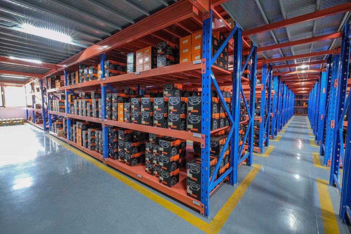
A receiving check of five minutes per carton catches most transit and labelling problems before they reach a customer.
- Part number, marking and quantity against the purchase order and the confirmed drawing.
- Preservative film intact, no bare metal, no condensation inside the bag.
- Seal lips seated, no cuts or deformation; encoder ring clean and undamaged.
- Free rotation by hand, smooth with no roughness or catch; no detectable axial play on a sealed unit.
- Flange flatness and bolt hole condition; spline burr-free.
- Packaging, label artwork and private-label print match the approved proof.
Frequently Asked Questions
How can you tell which generation of hub bearing a vehicle uses?
Look at how the bearing meets the knuckle. If the bearing is pressed into the knuckle and the hub is a separate part, it is generation 1. If the bearing has its own bolted flange but the hub shaft is separate, it is generation 2. If one unit carries the wheel bolt circle and the ABS ring and bolts straight on, it is generation 3.
Can a hub bearing be regreased or repaired instead of replaced?
No, not in practice. Sealed hub units are filled for life and the seals are destroyed by disassembly, and a bearing that has already produced noise has raceway damage that new grease cannot remove. Separate first-generation bearings can be cleaned and repacked only where the design allows it and the races are still unmarked.
What does pre-set preload mean for an importer?
It means the internal setting is fixed at assembly, so the workshop cannot adjust it and the part must match the application exactly. For an importer this raises the value of the drawing: if the preload, grease fill and seal are not defined and confirmed, two batches from two sources can look identical and behave differently on the vehicle.
What should be agreed before a custom hub bearing order?
Agree the drawing with all interface dimensions, the sample approval, the marking and packaging artwork, and the inspection items that will be recorded at dispatch. Jinan Huayuan Bearing develops parts from drawings and samples, supports custom packaging and private label, and serves mainly aftermarket and OE customers in the Middle East and Southeast Asia through huayuanbearing.com.
Purchasing guidance, product information and company updates from Huayuan Bearing.