
What Does затяжка ступичного подшипника Mean in Bearing Terms?
затяжка ступичного подшипника translates as “tightening of the hub bearing”, and in engineering terms it means the axial clamp load that holds the bearing rings in their designed working position on the spindle or in the knuckle. The nut is only the device that generates that load. Torque applied to the nut becomes a clamping force that travels through the inner ring, the rolling elements and the outer ring, and the bearing works as designed only when that force path is closed and stable.
If clamp load is lower than the forces acting on the corner — cornering loads, kerb impacts, the axial pull of a driven shaft — the ring can creep or fret on its seat. If clamp load is higher than the design allows, the rolling contact is overloaded and the grease film breaks down. Both extremes end in the same place: noise, play and a repeat repair.
Which Three Operations Does the Term Cover?
The phrase is used loosely, so it helps to separate three jobs that share one principle:
- Setting preload or end-play on an adjustable bearing pair. On serviceable opposed tapered roller designs the nut is an adjustment device: the fitter sets the running clearance and then locks the setting.
- Final torque of the axle nut on a sealed hub unit. On generation 2 and generation 3 units the preload is built in at manufacture, so the nut only clamps the unit to the shaft or to the outer constant-velocity (CV) joint.
- Torque of the mounting fasteners. Generation 2 and 3 hubs are often fixed to the knuckle by three or four bolts, and those bolts have their own specification. The same clamp-load logic applies to the centre nut of a constant-velocity joint and to the mounting bolt of a belt tensioner pulley.
Why Clamp Load, Not Torque, Is the Real Target
Torque is only a proxy for clamp load, because most of the wrench effort is consumed by friction in the thread and under the nut face rather than by stretching the fastener. A value measured on dry, coated threads and a value measured on oiled threads therefore produce different clamping forces from the same wrench setting. A usable specification states the thread condition, the nut type and whether a washer is fitted — and the fitter has to follow it rather than adding a little extra for safety.
How Do Generation 1, 2 and 3 Hub Units Differ in Tightening?
The generation of the hub unit decides whether tightening sets the bearing’s internal preload or merely clamps an already-preloaded unit to the vehicle. That single difference is why a torque figure from one car cannot be transferred to another, even when the two bearings look similar from the outside.
Generation 1: The Nut Is an Adjustment Device
A generation 1 bearing is a separate double-row unit — angular contact ball or tapered roller — pressed into the knuckle or onto the hub, with the two inner rings facing each other. On non-driven axles the retaining nut or a collapsible spacer sets the axial position of the inner rings, so tightening directly changes internal clearance. Too loose and the wheel has play and the rollers skid; too tight and the pair runs hot. The setting is verified by end-play measurement or rolling resistance, not by feel.
Generation 2: Flange Bolted to the Knuckle
In a generation 2 unit the outer ring carries a flange that bolts to the knuckle, while the inner rings are clamped on the spindle. The cartridge is sealed and preloaded by the bearing manufacturer, so the mounting bolts and the axle nut locate it and carry the corner loads. Bolt condition matters: stretched, corroded or reused bolts will not hold the clamp load the knuckle was designed for.
Generation 3: Sealed Unit, Nut Clamps the Shaft
A generation 3 hub integrates the wheel flange, the bearing rows and the ABS encoder ring in one sealed assembly. Preload is set on the production line by matching the ring widths, so the axle nut cannot add preload — it only clamps the inner ring against the outer CV joint. Over-tightening here does not seat the bearing; it loads the thread, the joint cage and the inner ring shoulder, and it can disturb the encoder signal.
Heavy Commercial and Trailer Hubs
Larger vehicles usually keep an adjustable opposed tapered roller pair with two nuts and a lock ring, or a single nut with a locking plate. Adjustment is a measured operation: the wheel is rotated while the nut is set, then end-play is checked and the lock engaged. Workshops that skip the measurement and rely on torque alone are a common source of premature heavy-hub failures. Adjustable designs of this type, together with sealed passenger-car hub units, are both covered by the same fitting logic but need different verification steps.
| Hub design | What tightening actually does | What sets the internal preload | What the fitter must verify |
|---|---|---|---|
| Generation 1, adjustable pair | Moves the inner rings axially and changes clearance | The nut or spacer setting made during fitting | End-play or rolling resistance after setting; lock engaged |
| Generation 2, flanged cartridge | Clamps the unit to the knuckle and the spindle | The bearing manufacturer, at assembly | Bolt condition and tightening sequence; nut type and thread state |
| Generation 3, integrated hub | Clamps the inner ring to the CV joint or spindle only | The bearing manufacturer, by matched ring width | Nut is new and correctly staked; encoder ring undamaged |
| Heavy truck or trailer pair | Sets bearing adjustment, then locks it | The adjustment procedure and the lock ring | Measured end-play, lock engagement, free rotation |
Which Torque Value Applies to a Hub Bearing, and Where Does It Come From?
There is no universal hub bearing tightening torque: the correct figure is defined per part number and per vehicle application, and it has to come from the vehicle manufacturer’s workshop data or from the bearing drawing. Any figure quoted without those two references is a guess, however often it appears in forums.
Which Inputs Define the Number
- Thread size and pitch — a fine thread converts torque into clamp load differently from a coarse one.
- Fastener grade and coating — property class, plating and any pre-applied locking compound change friction.
- Nut type — plain, nylon-insert, all-metal self-locking, staked or crimped, torque-to-yield. Several of these are single-use.
- Bearing design — an adjustable pair is set by clearance; a sealed unit is set by the manufacturer.
- Joint condition — clean, dry, burr-free threads and a flat, undamaged nut face are part of the specification, not preparation details.
Which Tightening Method Fits Which Hub
Four methods appear in workshop data and they are not interchangeable. A torque wrench to a stated figure is the common case for hub nuts with a defined clamp load. Torque plus angle is used where the fastener is designed to yield and the angle, not the final torque, controls the clamp. Rolling resistance or preload measurement is used on adjustable pairs where clearance is the target, and a dial indicator is used where the specification is written as end-play.
| Method | What it controls | Where it is used | What goes wrong if misapplied |
|---|---|---|---|
| Torque wrench to a stated figure | Clamp load through a known thread friction | Axle nut on a sealed hub unit | Wrong thread condition gives the wrong clamp load |
| Torque plus angle | Stretch of a yielding fastener | Some flange and suspension fasteners | Reusing the fastener removes the intended stretch |
| Rolling resistance or preload gauge | Internal bearing preload | Adjustable tapered roller pairs | Dry seals or fresh grease can mislead the reading |
| Dial indicator end-play | Running clearance | Heavy truck and trailer hubs | Measuring with the wheel fitted shows false play |
Why a Value From Another Car Is Not Transferable
Spindle diameter, nut thread, bearing width and knuckle stiffness all enter the calculation, and two vehicles on the same wheel size can use completely different clamp loads. When the workshop data is missing, the reliable route is the part supplier’s technical data for that specific number, checked against the drawing — not a figure borrowed from a similar model. Where a part is developed to a customer drawing, the tightening note on that drawing governs both production and installation.
How Should a Hub Bearing Be Tightened, Step by Step?
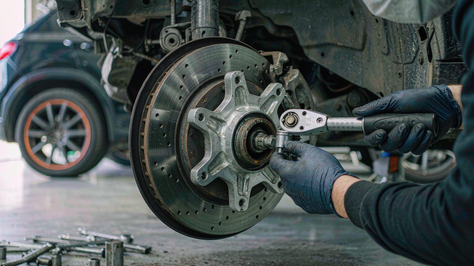
Tighten a hub bearing by confirming the specification and the fastener first, then applying load in stages with a calibrated wrench and verifying the result before the vehicle leaves the bay. The sequence below follows the order that prevents the common installation faults; the actual figures always come from the workshop data or the drawing.
- Identify the part and the specification. Match the hub to its drawing or sample reference and read the tightening note before touching the nut. Confirm whether the nut is single-use.
- Clean and inspect the spindle and housing. Remove old locking compound, burrs and corrosion. A raised burr on the spindle shoulder tilts the inner ring and destroys the preload.
- Check the new unit before fitting. Rotate it by hand, listen for roughness, confirm the seal lips are intact and the encoder ring is present on ABS versions.
- Seat the unit square. Press or draw it in on the outer ring for a knuckle fit, and never transmit press force through the rolling elements.
- Fit the correct fastener. Use the specified nut and washer, and replace staked, crimped and torque-to-yield fasteners rather than reusing them.
- Hold the hub correctly. Counter-hold on the flange or a dedicated tool, not on the wheel studs, and never let the shaft turn against the parking pawl.
- Apply load in stages. Bring the nut up to roughly half the specified figure, check that the unit is seated, then continue to the final value in one smooth pull.
- Verify the setting. Check rotation for roughness and, on adjustable designs, measure end-play or rolling resistance as the specification requires.
- Lock the fastener. Stake, crimp or fit the lock ring exactly as specified; a staked nut that is not staked can back off in service.
- Complete the corner. Refit the wheel, torque the wheel fasteners, and where the data requires it apply the final hub torque with the vehicle on the ground.
- Road test and re-check. Listen for speed-related noise and, on heavy or adjustable hubs, re-check play after the first loaded run.
What Causes Hub Bearing Failure, and How Do You Read the Evidence?
Most hub bearing failures that follow a repair trace back to clamp load and installation, not to the steel. Reading the failure signature — where the wear sits, what colour the rollers are, which direction the play appears in — usually identifies the cause before the part is replaced.
Too Little Clamp Load
A nut that was never staked, a reused self-locking nut, a missing washer or a damaged thread all reduce clamp load. The inner ring then moves microscopically on the spindle and fretting follows: a polished seat with reddish-brown oxide dust. The driver notices play, a knock over bumps and, on driven hubs, a wandering ABS signal.
Too Much Clamp Load
Over-tightening an adjustable pair removes running clearance. The evidence is heat: blue or straw-coloured rollers, grease that has bled past the seal, cage pockets worn at the roller ends, and spalling that starts at the raceway edge instead of the centre of the load zone.
Contamination and Seal Damage
A torn seal lip, a missing dust shield or a unit pressed in by its inner ring gives water and grit a route to the raceway. Look for rust streaks in the load zone, emulsified grey grease and fine lapping wear rather than classic fatigue spalling. Cleaning a sealed hub with a pressure washer aimed at the seal produces the same result with no fitting error at all.
Impact and Misalignment
Kerb strikes bend the flange and brinell the raceways, leaving the roller imprint as evenly spaced dimples. A knuckle face that was not cleaned, or a bent mounting flange, tilts a generation 2 or 3 unit so that wear becomes one-sided across the row.
| Symptom | Most likely cause | What to check |
|---|---|---|
| Play felt at the top and bottom of the wheel | Loose or backed-off nut, worn adjustable pair | Nut lock, thread condition, measured end-play |
| Play at the front and rear of the wheel | Steering or suspension joint rather than the bearing | Track rod and ball joint before replacing the hub |
| Hum that rises with road speed and changes in a turn | Raceway fatigue from overload or contamination | Strip the unit and inspect the load zone |
| Grease weeping from the seal | Over-tightening, blocked breather or a damaged lip | Seal lip, grease colour, roller discolouration |
| ABS light after a hub replacement | Encoder ring damaged or fitted the wrong way round | Ring condition, air gap, harness routing |
Which Design Details Decide How a Hub Unit Behaves Under Clamp Load?
Raceway geometry, material and heat treatment, clearance class and sealing decide how much clamp load a hub unit can carry and how long it keeps it. Two units with identical mounting dimensions can behave very differently in service when these four details differ.
Tapered Roller, Double-Row Ball or Cylindrical Roller
Tapered roller bearings carry combined radial and axial loads and suit adjustable hubs and heavier vehicles, but they need a defined preload to keep the rollers in contact. Double-row angular contact ball bearings dominate passenger-car generation 2 and 3 units because they are compact, preloadable at assembly and low in friction. Cylindrical roller bearings carry high radial load in a small envelope but take no axial load on their own, so they appear only where a separate thrust face exists.
Material and Heat Treatment
Rings and rolling elements are normally made from through-hardening bearing steel such as 100Cr6 or GCr15, hardened and tempered to a specification that balances hardness against toughness. Flange and hub bodies are forged or machined from medium-carbon steel, with seat and spline areas induction hardened where the drawing requires it. Hardness, case depth and microstructure are drawing-controlled characteristics, confirmed by process data rather than judged by appearance.
Clearance, Preload and Tolerance Class
Radial internal clearance and tolerance class are separate specifications. Tolerance class (ISO 492 normal, P6 or P5) governs dimensional and running accuracy; clearance governs how much internal slack the assembled bearing has. In a sealed hub unit the clearance is already converted into preload by matched ring widths, which is why the customer cannot adjust it and should not try.
Seals, Grease and the Encoder Ring
Sealing is what separates a long-life hub from a short-life one in a dusty or wet market. Multi-lip seals with a greased intermediate chamber, a metal slinger and a protected encoder ring are the practical minimum for aftermarket conditions in hot, dusty regions. Grease fill is set for life in a sealed unit; forcing grease past a damaged lip only introduces contamination.
What Should You Check on the Drawing and at Goods-In?
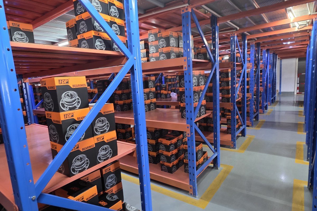
Two checks prevent most hub bearing complaints: reading the drawing before the order is placed and inspecting the shipment against that drawing when it arrives. Neither step needs a laboratory, and both catch errors that are expensive to correct after the container has cleared customs.
Reading the Drawing Before Ordering
The drawing is the only reliable definition of a hub unit. The parameters that decide fit are the bore and outer diameter, the overall width, the flange diameter and offset, the bolt-hole pitch circle and hole count, the thread or spline, the ABS sensor type and its angular position, and the seal arrangement. Part numbers and OE references are leads, not proof: the fit is confirmed by drawing and sample, because one reference can cover different flange and sensor variants across model years.
Inspecting a Delivery
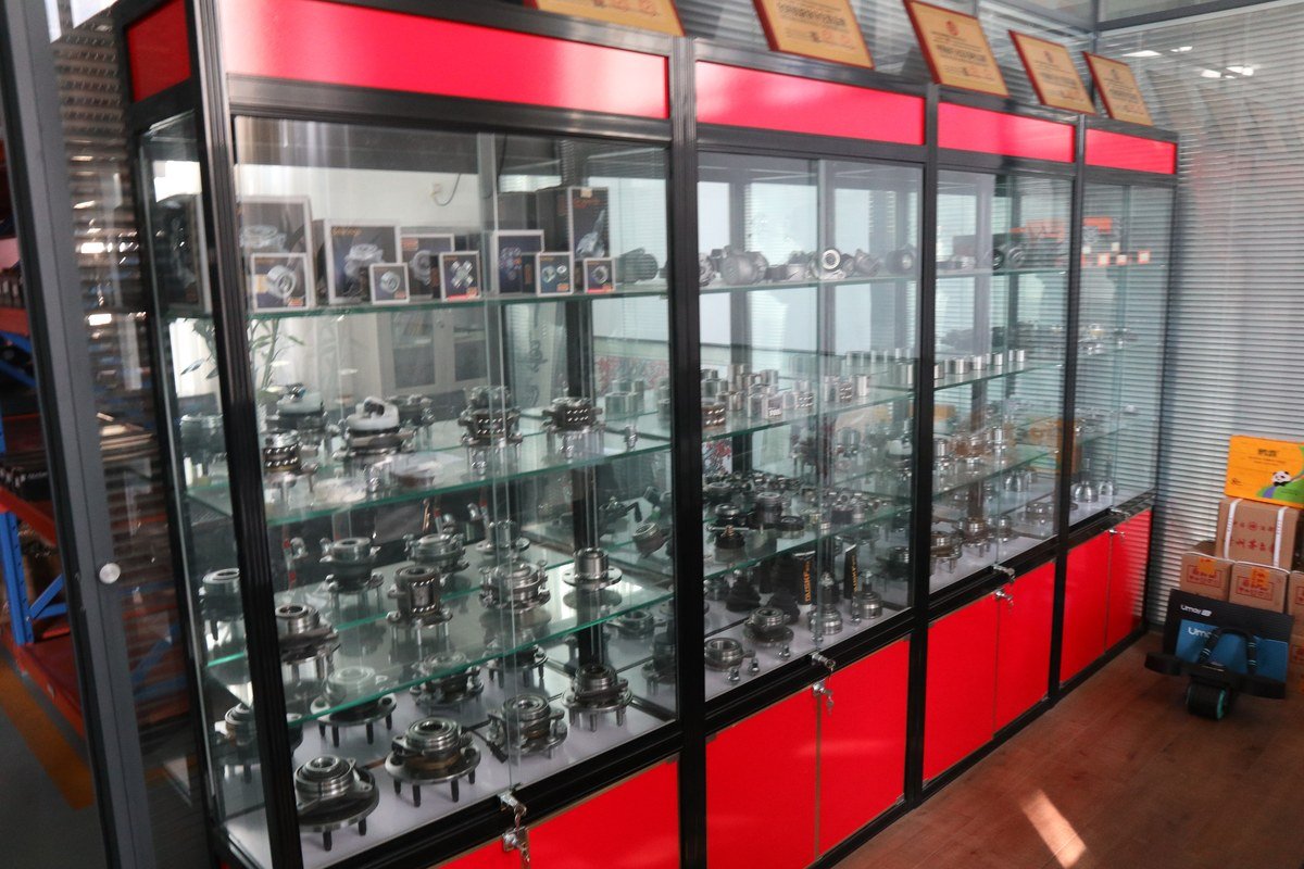
- Dimensions: spot-check bore, flange offset and bolt pattern against the drawing.
- Rotation: smooth and quiet by hand, with no tight spot and no axial rock.
- Seals: lips undistorted, slinger seated, no grease on the outside of the unit.
- Encoder: ring present, flat and undamaged on ABS versions.
- Marking and packaging: part number matches the purchase order and the private-label artwork; cartons undamaged and quantities correct.
Where Huayuan Bearing Fits
Jinan Huayuan Bearing Co., Ltd. is a bearing manufacturer and exporter based in Jinan, Shandong, producing wheel hub bearings and hub units together with tensioner pulleys and CV joints for aftermarket replacement and OE supply. The company develops parts to customer drawings and samples, supports custom packaging and private-label programmes, and serves overseas buyers mainly in the Middle East and Southeast Asia. The product scope behind huayuanbearing.com is listed on the huayuanbearing.com product pages, and the tightening note that applies to any specific part is confirmed by drawing and sample.
Frequently Asked Questions
Does a hub nut have to be replaced every time?
Not every nut, but every single-use type: staked, crimped, nylon-insert and torque-to-yield fasteners are designed to be replaced once removed, because the locking feature or the stretch is consumed. Where the workshop data lists a reusable nut, check the thread and the seating face before refitting it.
What happens if a wheel hub bearing is overtightened?
On an adjustable pair, over-tightening removes running clearance and the bearing overheats, which shows as discoloured rollers, bled grease and early spalling. On a sealed generation 3 unit the internal preload cannot change, but excess torque can damage the thread, the CV joint or the inner ring shoulder. In both cases the repair is replacement, not loosening.
Is the tightening torque the same on both sides of the car?
Usually yes for a given axle, but not always: driven and non-driven corners can use different hubs and different fasteners, and left and right threads are occasionally reversed on older designs. Confirm per corner against the workshop data rather than assuming symmetry.
Can a hub bearing be tightened by feel instead of a torque wrench?
No. Feel cannot reproduce clamp load consistently, and friction variation between dry and lubricated threads is larger than the tolerance most hub nuts allow. A calibrated torque wrench, the specified thread condition and the correct tightening sequence are the minimum for a repeatable result.
Purchasing guidance, product information and company updates from Huayuan Bearing.