
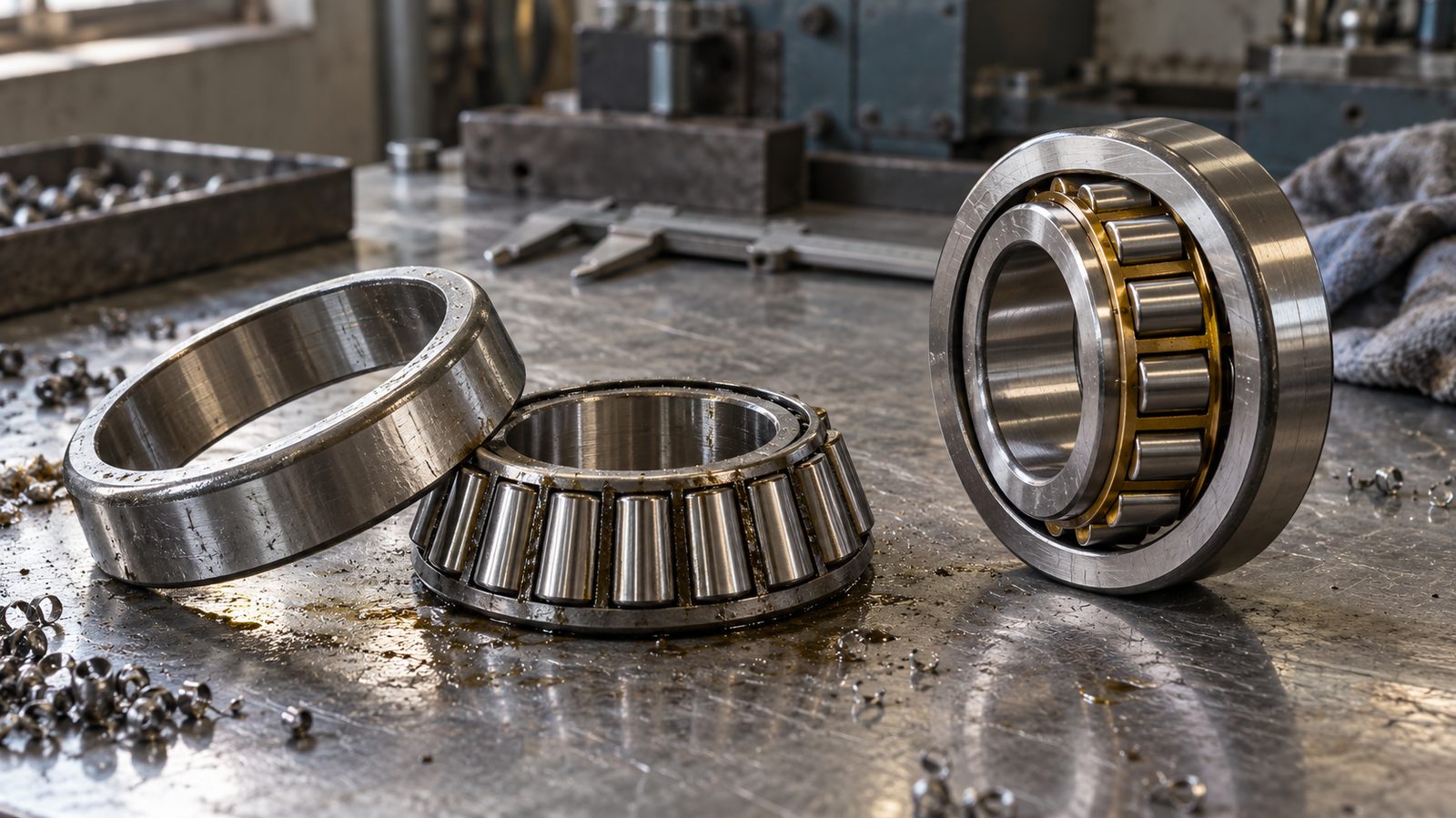
The short answer: tapered and cylindrical roller bearings are separated by load direction. A tapered roller bearing runs conical rollers on angled cone and cup raceways, so it carries combined radial and axial load and can be set to a defined endplay or preload. A cylindrical roller bearing runs parallel rollers on parallel raceways, so it carries very high radial load and almost no axial load. Tapered suits wheel ends, pinions and differentials; cylindrical suits gearbox shafts, motors and other radial-heavy, high-speed positions. huayuanbearing.com manufactures both families for aftermarket and OE replacement programmes.
What Is the Difference Between Tapered and Cylindrical Roller Bearings?
Tapered and cylindrical roller bearings differ in roller shape, raceway angle and therefore load direction: a tapered roller bearing rolls on an inclined contact line and carries combined radial and axial load, while a cylindrical roller bearing rolls on a contact line parallel to the shaft axis and carries radial load only, with a higher radial rating and higher stiffness in the same envelope. Every other practical difference — mounting arrangement, clearance setting, friction, speed limit and failure pattern — follows from that geometry.
How Does Roller Geometry Decide Load Direction?
A tapered roller bearing uses conical rollers between a cone (inner ring) raceway and a cup (outer ring) raceway machined at an angle to the shaft axis. The raceway extensions and the roller apex meet at a single point on the axis, which is what lets the roller roll instead of scrub, and the resulting contact angle resolves part of the applied load into the axial direction. A single row carries thrust in one direction only, so a located shaft needs two rows in opposition, a matched pair or a double-row design.
A cylindrical roller bearing uses cylinders with parallel axes between cylindrical raceways, so the contact angle is zero and the design load path is purely radial. Ribs on the rings keep the rollers aligned and resist skew; in the NU and N designs they act as guides only, while the NJ and NUP designs add a locating rib so the bearing can hold a shaft axially in one direction against light thrust. Most cylindrical designs are separable, which simplifies mounting and inspection.
Cylindrical roller bearings normally show the higher radial dynamic load rating for a given section height: the roller is long in relation to its diameter, the contact line runs the full effective roller length, and no capacity is traded away for thrust. Tapered bearings accept that trade because the axial location they provide is often the reason the position was designed around them.
What Do the Two Designs Look Like Side by Side?
The table compares the families on the points importers, channel buyers and maintenance engineers usually ask about. Ratings and speed limits vary by size and series, so treat the pattern as a rule of thumb and confirm the numbers on the drawing.
| Feature | Tapered roller bearing | Cylindrical roller bearing |
|---|---|---|
| Roller form | Truncated cone | Cylinder with parallel axis |
| Raceway angle | Inclined to the axis; contact angle is typically 10°–16° in standard single-row metric series, wider in steep-angle designs | Parallel to the axis; contact angle zero |
| Load carried | Combined radial and axial, one axial direction per row | Radial; axial only as a light locating load in NJ and NUP designs |
| Radial rating, same envelope | Lower, because capacity is shared with thrust | Higher of the two |
| Radial stiffness | High | Very high, full-length line contact |
| Friction and torque | Higher, from roller end and rib sliding | Lower |
| Speed capability | Lower | Higher |
| Axial location of shaft | Built in when two rows are paired and set | Only with a locating rib; NU and N designs allow axial float |
| Typical mounting | Two single rows in opposition, a matched pair or a double row | Single row, a locating and floating arrangement, or a double row |
| Automotive positions | Non-driven wheel hubs, pinion heads, differential carriers, trailer axles | Gearbox shafts, transfer case shafts, some motor and accessory drives |
| Common metric designations | 30204, 32206, 32307 | NU204, NJ206, NUP210, NN3010 |
Read the table as a set of trade-offs, not a ranking. A gearbox shaft does not need the axial stiffness of a tapered pair, and a wheel end cannot be allowed the axial float of an NU bearing. The full dimensional range for the inclined design is listed on the huayuanbearing.com tapered roller bearing product page.
Which Load Case Points to a Tapered or a Cylindrical Roller Bearing?
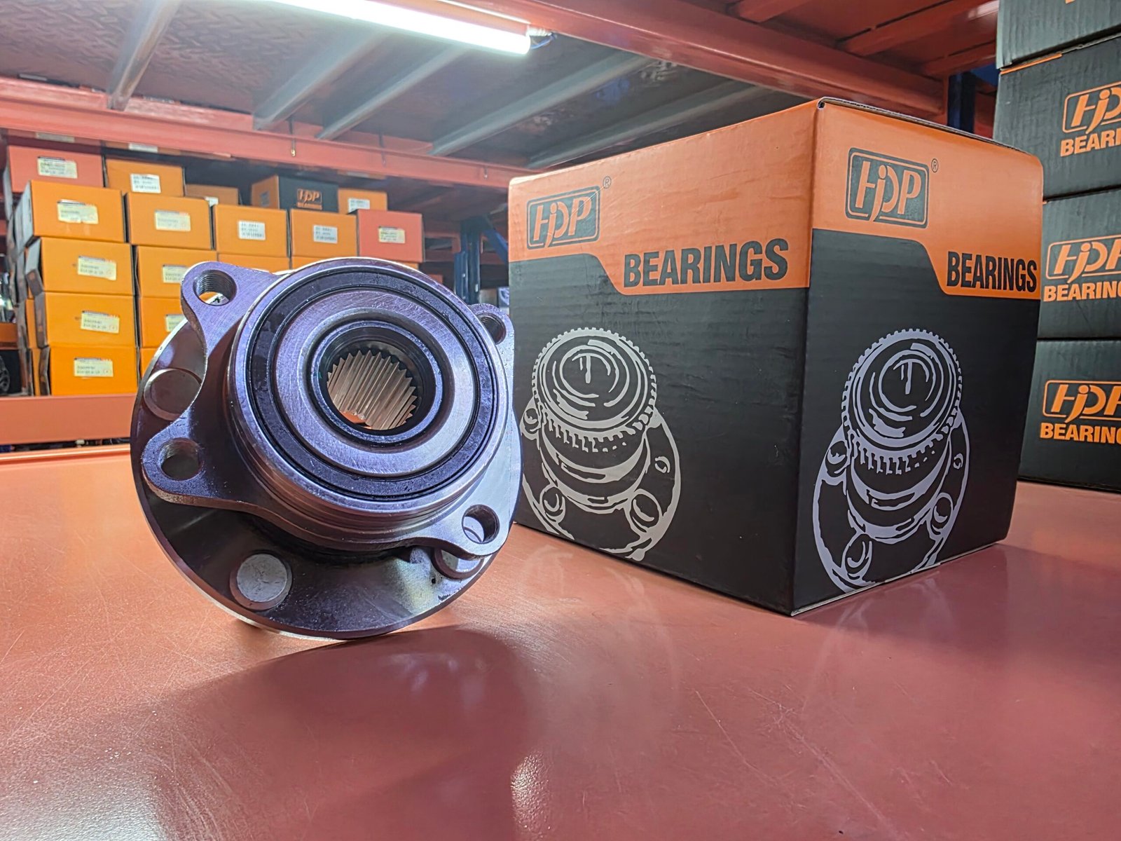
The load case decides the family before the part number is opened: radial load alone points to cylindrical, combined radial and axial load points to tapered, and thrust that must be carried in both directions points to two tapered rows in opposition.
When Does Radial Load Alone Point to a Cylindrical Roller Bearing?
High radial load at moderate or high speed points to a cylindrical roller bearing. Gearbox shafts, electric motor and generator shafts, industrial reducers, fan shafts, conveyors and crushers all belong to this group, because the shaft mainly has to be held radially and kept stiff so that gears stay in mesh and deflections stay small. In a locating and floating arrangement one bearing locates the shaft (NJ or NUP) while the other (NU or N) can slide axially in its housing, so thermal growth does not load either bearing. Radial-heavy positions therefore start from the cylindrical roller bearing range rather than from a thrust-capable design.
When Does Combined Load Point to a Tapered Roller Bearing?
Combined load with a real axial component points to a tapered roller bearing. Wheel ends, differential pinions, differential carriers and trailer axles all generate thrust as well as radial load, and the hypoid offset in a final drive produces a steady axial force that only an angled bearing can absorb. Because one row takes thrust in one direction, these positions use two single rows mounted in opposition, a matched pair, or a double-row tapered unit.
How Is the Shaft Located Axially in Each Design?
Axial location is built in with tapered bearings and added with ribs or separate components with cylindrical bearings. A tapered pair is set at assembly — by shim, spacer, adjusting nut or crush sleeve — to a defined endplay or preload, and that setting is part of the bearing function, not an installation detail. A cylindrical bearing locates only if it has a locating rib, and even then the rib is not intended for sustained heavy thrust; heavy thrust belongs to a tapered or angular contact bearing, or to a separate thrust bearing.
Use the matrix below to sanity-check a position before comparing dimensions.
| Position | Dominant load | Usual choice | Reason |
|---|---|---|---|
| Non-driven wheel hub (trailer, light truck) | Radial plus cornering thrust | Opposed single-row tapered pair | Adjustable endplay and rebuildable |
| Driven wheel hub | Radial plus wheel moment | Double-row angular contact hub unit | Integrated flange, seals and sensor ring |
| Differential pinion head | Radial plus steady thrust | Tapered, often steep angle | Hypoid mesh generates axial force |
| Differential carrier | Radial plus thrust in both directions | Tapered pair | Locates the carrier and absorbs gear separating force |
| Gearbox input and output shafts | Radial, high | Cylindrical NU, NJ or NUP | Highest radial capacity with controlled float |
| Electric motor shaft | Radial, high speed | Cylindrical | Lower friction at speed |
| Tensioner or idler pulley | Light radial, oscillating | Sealed ball or needle roller | Sealed for life and compact |
| Industrial pump or fan shaft | Radial | Cylindrical | Stiffness and load rating |
How Do Roller Profile, Cage and Clearance Change Real Performance?
Two bearings with identical boundary dimensions can perform very differently, because roller profile, cage material, steel grade and clearance group set the actual life, noise and running temperature.
Why Is Roller Profile More Than a Manufacturing Detail?
A crowned or logarithmically profiled roller avoids stress concentration at the roller ends. A roller with a sharp edge, or a bearing sitting misaligned in its housing, loads the ends of the contact line first and spalls there long before the calculated life is reached. Profile is also why misalignment matters more for a roller bearing than for a ball bearing: the longer the contact line, the less angular error the bearing tolerates.
Which Cage Material Should You Expect?
Pressed steel cages are the volume standard for automotive and industrial bearings, machined brass cages are chosen for shock load, high temperature and long service intervals, and glass-filled polyamide cages appear where low mass, low noise and grease retention matter. Cage type also changes grease capacity and maximum speed, so a change of cage type is a design change and should be confirmed against the drawing rather than assumed from the part number.
How Do Clearance Groups and Bearing Setting Differ Between the Two Types?
Cylindrical roller bearings are ordered by radial internal clearance group — C2, CN, C3 or C4 — and the correct group depends on fits, housing material and operating temperature. Tapered roller bearings are instead set axially at assembly, measured as endplay or preload across the pair. Both approaches answer one question: how much internal space the bearing needs once it reaches operating temperature. Too little clearance or too much preload gives heat, grease breakdown and seizure; too much clearance gives roller skew, noise and hammering of the raceway. Ring and roller steel, and its heat treatment, set the ceiling on all of this: through-hardened GCr15 or 100Cr6 is the default, with case-carburising used where shock load is expected, and bearing steel grade and heat treatment explains what to put in a specification.
Which Bearing Goes Where on a Vehicle or Machine?
Position tells you the load case, and the load case tells you the bearing family, which is why one vehicle can use tapered, cylindrical, angular contact and ball bearings within a metre of each other.
Which Bearings Sit at the Wheel End?
Non-driven hubs have historically used two single-row tapered roller bearings in opposition, set to a defined endplay, and that arrangement is still common on trailers, light trucks and older rear-wheel-drive cars because it can be adjusted and rebuilt. Driven hubs have largely moved to hub units: a double-row angular contact bearing with integrated seals, in the second generation with a flange on the outer ring, and in the third generation with a flange on the inner ring and an ABS sensor ring. The two are not interchangeable, and wheel hub bearing versus wheel hub assembly sets out the difference in rebuild terms.
Which Bearings Work in the Gearbox and Final Drive?
Gearbox shafts run on cylindrical roller bearings because radial capacity and stiffness dominate and axial float has to be controlled. The final drive reverses the priority: the pinion head and the differential carrier see thrust from the hypoid mesh, so they run on tapered roller bearings, often as a paired or double-row arrangement that is set during assembly.
Which Bearings Run on Tensioners and Accessory Drives?
Tensioner and idler pulleys carry light radial load with small oscillating movement, so they use sealed-for-life ball or needle roller bearings rather than tapered or cylindrical rollers. The dominant risk in that position is not fatigue but false brinelling and grease starvation, so the seal and grease specification matters more than the headline load rating.
Where Does the Same Logic Apply Outside Vehicles?
The same logic applies to industrial machines: pump and fan shafts, conveyors, mixers, crushers and rolling mill stands take radial load and use cylindrical roller bearings, while equipment with an axial component — screw conveyors, some pump shafts, bevel gearboxes — uses tapered or angular contact bearings. huayuanbearing.com manufactures tapered and cylindrical roller bearings alongside wheel hub bearings and hub units, tensioners and CV joints for aftermarket and OE replacement programmes, with development to drawing and sample.
How Do You Confirm a Replacement Bearing From a Drawing?
A replacement is confirmed by dimension, internal geometry and marking, not by a vehicle list: two bearings that fit the same bore can differ in contact angle, clearance, cage and seal, and the difference only appears in service.
Which Parameters Must Match on the Drawing?
Check the boundary dimensions first — bore, outer diameter and width or total width — then the parameters that are invisible once the bearing is fitted. A usable drawing or sample confirmation should state all of the following.
- Bore, outer diameter and width with tolerances, plus the accuracy grade (P0, P6, P5 or P4).
- Contact angle for tapered designs, and the cone and cup assembly height where the part is matched.
- Radial internal clearance group for cylindrical designs, or the axial setting for a tapered pair.
- Roller count, roller profile, and cage type and material.
- Corner radii and shoulder diameters, which decide whether the bearing seats correctly.
- Seal or shield type, grease quantity and fill percentage, and whether the part is pre-greased.
- Marking, including any required neutral or customer-brand packaging.
How Do You Confirm a Part in Seven Steps?
- Identify the position and its load case, not only the old part number.
- Measure the housing bore, shaft seat, width and shoulder positions on the actual unit.
- Read the marking on the old bearing and record the full designation, including any suffix.
- Compare internal geometry — roller count, cage, contact angle or clearance group — against the drawing.
- Confirm the seal and grease specification against the operating environment.
- Check the axial setting method for tapered positions and the clearance group for cylindrical ones.
- Approve a sample against the drawing before releasing volume, and keep that approved drawing as the reference for later shipments.
Where a model or OE number is involved, treat the cross-reference as a lead rather than a confirmation, and confirm fitment by drawing and sample. Buyers who pass specifications to a Chinese-speaking engineering team can work from the same series on the Chinese-language tapered roller bearing pages; Russian-speaking teams use the matching Russian-language cylindrical roller bearing pages.
What Do These Bearings Fail From, and What Should You Check at Goods-In?

Most roller bearing failures are visible in the contact pattern before they are audible, and the pattern usually names the cause: setting, lubrication, contamination, mounting or load.
What Does the Failure Pattern Tell You?
Read the surface, not the noise. The table maps the common patterns to the cause they most often indicate.
| Symptom | What it usually means | What to check next |
|---|---|---|
| Spalling along the raceway centre | Fatigue at end of life, or overload | Actual load, alignment, lubrication interval |
| Indentations spaced at roller pitch | Brinelling from impact or transport vibration | Handling, packaging and storage practice |
| Blue or straw discolouration with hardened grease | Overheating from excess preload or wrong setting | Axial setting, clearance group, grease quantity |
| Rust lines or pitting along the roller path | Moisture ingress | Seal condition, storage, washing practice |
| Wear step or scoring on the rib face | Lubrication failure at the roller end | Grease type, fill level, speed |
| Skewed, polished roller marks and cage pocket wear | Misalignment or roller skew | Housing and shaft alignment, seat condition |
| Cut seal lip or displaced garter spring | Mounting damage | Fitting method and tooling |
What Should a Goods-In Check Cover?
Acceptance checks are cheap compared with a claim, so verify the shipment against the approved drawing rather than against a catalogue page.
- Packaging and preservative: carton condition, rust preventive film, no free moisture.
- Marking: designation, agreed brand or neutral marking, and batch traceability.
- Dimensions: bore, outer diameter and width measured on a sample against the drawing.
- Rotation: smooth and free running, with no axial play beyond the specified setting.
- Internal features: roller count, cage type, seal lip and presence of grease.
- Documents: drawing revision and inspection record matching the shipment.
A short, repeatable goods-in inspection routine catches most substitution problems before stock reaches a workshop.
Frequently Asked Questions
Is a tapered roller bearing stronger than a cylindrical roller bearing?
Neither is stronger in general; they are rated for different loads. For pure radial load in the same envelope, a cylindrical roller bearing has the higher dynamic rating and stiffness. A tapered roller bearing is stronger where the load has an axial component, because it carries thrust that a cylindrical bearing cannot and locates the shaft at the same time.
Can a cylindrical roller bearing be replaced by a tapered roller bearing?
Usually not as a like-for-like swap. A tapered bearing needs an axial setting, adds friction and reduces the speed capability of a position originally designed for float. An NJ or NUP locating bearing can sometimes be replaced by a tapered pair if the housing allows adjustment, but the change should be approved against the drawing and load calculation, not the bore size.
Why do tapered roller bearings need a preload or endplay setting?
Because the setting controls the internal clearance of the whole pair. Shims, spacers or an adjusting nut define how far the two rows sit apart, and that distance changes with temperature in service. The correct setting removes play without closing the running clearance, which is why a wheel end or a pinion is adjusted rather than simply replaced.
Which type runs cooler at high speed?
The cylindrical roller bearing, for two reasons: it has no thrust component to resolve, and no sustained sliding at a roller end rib. Tapered bearings generate more heat from roller end contact and from the axial load path, so their limiting speed is lower for the same size and lubrication. High-speed gearbox and motor shaft positions are therefore usually cylindrical.
Purchasing guidance, product information and company updates from Huayuan Bearing.