
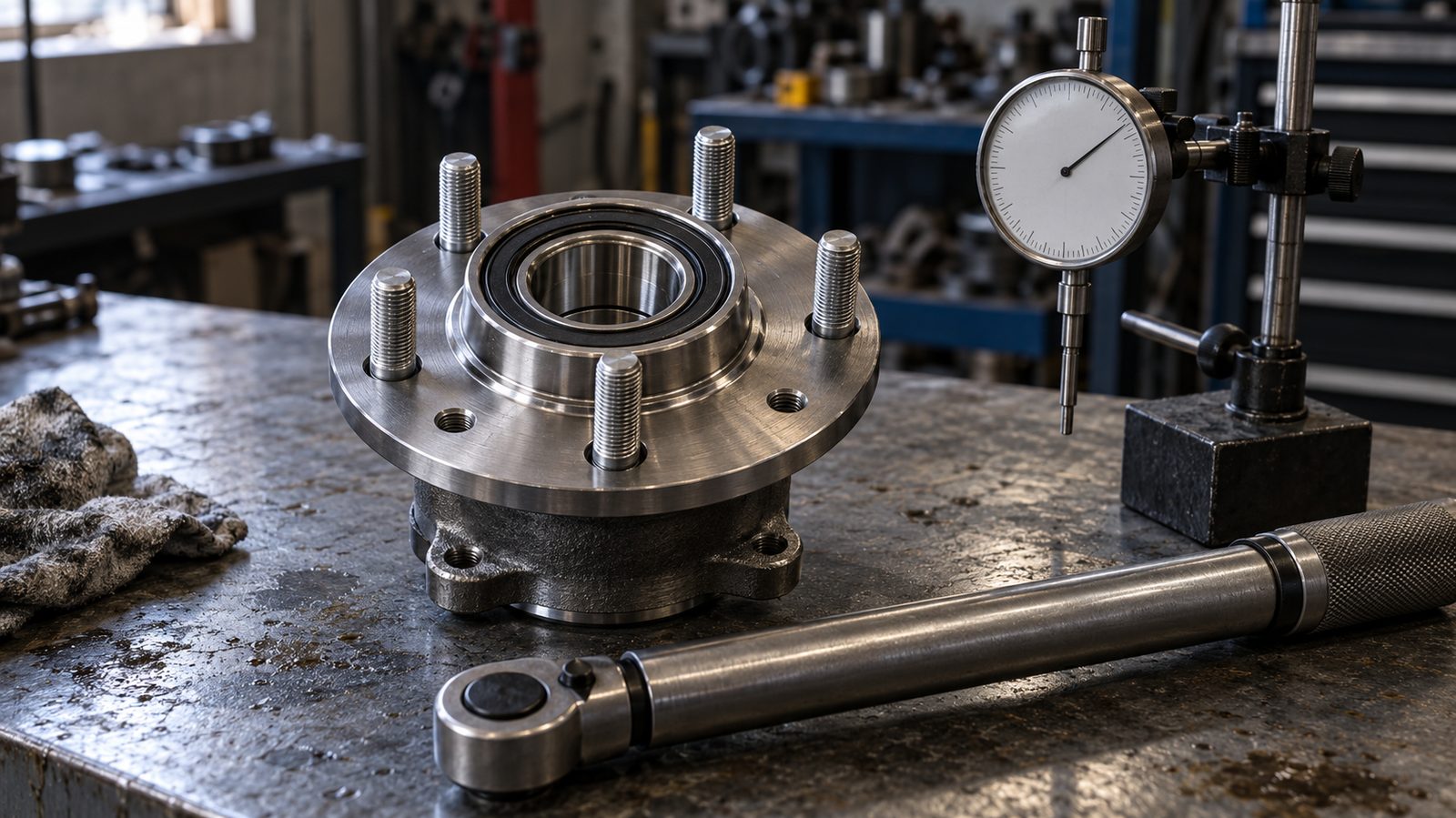
Wheel hub bearing installation torque and preload are two different settings handled in a fixed order: preload is the internal clamp force that keeps the rolling elements against both raceways, and axle nut torque is only the input used to create it. On sealed third-generation hub units the preload is built in during production, so the installer applies a specified torque — often torque plus angle — and makes no adjustment. On separate tapered roller bearings the nut position itself sets preload, and the result must be verified by rolling torque or end play. Mixing up the two cases is the most common cause of premature hub failure.
What Does Wheel Hub Bearing Installation Torque and Preload Actually Control?
Preload controls bearing life, running temperature and noise; installation torque is only the indirect means of producing it. Preload is the axial force that holds the balls or rollers against their raceways before any road load arrives. A correctly preloaded bearing runs with every rolling element sharing load, with no internal clearance to be taken up each time the wheel changes direction, and with a flange position that stays stable under cornering and braking. When preload is too low the rolling elements skid instead of roll, which polishes the raceway, wears the cage pockets and produces the whine or rumble that a workshop later diagnoses as a worn bearing. When preload is too high, contact stress and running temperature rise, the grease film thins and raceway fatigue life drops — and the part can still feel perfectly smooth by hand. Neither error is visible after the wheel is refitted, so the setting has to be correct at the bench.
Torque is a weak proxy for preload because of friction. Only part of the applied torque becomes axial clamp force; the remainder is consumed by thread friction and by friction under the nut face or bolt head. Those losses change with lubrication, plating, thread condition, washer presence and whether the fastener has already been used. This is exactly why specifications appear in two forms. A plain torque figure assumes a defined fastener condition and is simple but friction-dependent. A torque-plus-angle figure first seats the fastener, then rotates it through a fixed angle, so the final clamp load is governed by fastener stretch rather than by friction — which is why angle-controlled fasteners must never be reused or backed off.
Why the Axle Nut Is a Bearing-Setting Tool on Some Designs and a Clamp on Others
On a separate tapered roller bearing, the nut moves the inner cone along the spindle, so nut position literally defines preload: turn it in and preload rises, back it off and clearance returns. On a factory-set double-row angular contact hub bearing, the two inner rings are ground as a matched pair and the preload is fixed by that grind. Here the nut performs a completely different job — it clamps the hub and the CV joint outer race to the bearing inner ring so the joint cannot move axially. Same tool, same fastener, opposite meaning. A fitting instruction copied from one design to the other will either leave a joint loose or crush a bearing.
What Happens When Preload Is Wrong in Each Direction
Under-preload shows up first as noise at low speed and as movement felt when the wheel is rocked at twelve and six o'clock. Over-preload shows up first as heat: a hub that is noticeably warmer than its opposite number after a short drive, grease that darkens and smells burnt, and eventually blue or discoloured raceways with flaking rather than the even matte wear pattern of a normal bearing. Both conditions shorten life, but only under-preload can sometimes be corrected by re-torquing an adjustable arrangement; over-preload on a sealed unit means replacement, because the raceways have already been stressed beyond their design contact pressure.
Which Wheel Hub Bearing Types Need a Preload Setting?
Only an adjustable, non-sealed bearing arrangement needs the installer to set preload; sealed hub bearings and hub assemblies are preloaded during production and require the correct clamp torque only. Nearly all confusion around this topic comes from applying one rule to both families. The table below separates them by what the fastener actually does.
| Arrangement | Typical use | Preload set by | Fastener role | How it is verified |
|---|---|---|---|---|
| Separate tapered roller pair (cone and cup) | Older rear-wheel-drive front hubs, trailer axles, light truck | Installer, through nut position or spacer | Adjusts preload directly | Rolling torque or end play |
| Angular contact pair with shims | Some industrial and gearbox shafts | Shim thickness chosen at assembly | Clamps the stack | End play with dial indicator |
| First-generation hub bearing | Sealed cartridge in knuckle or hub | Factory, matched inner rings | Clamps the joint | Correct torque only |
| Second-generation hub bearing | Flanged outer ring bolted to knuckle or drum | Factory | Bolts clamp the flange, nut clamps the shaft | Correct torque and bolt sequence |
| Third-generation hub unit | Most passenger cars, ABS equipped | Factory | Axle nut clamps CV joint to inner ring | Torque plus angle, no adjustment |
| Tensioner pulley bearing | Belt drive accessory | Factory, sealed for life | Bolt clamps pulley to bracket | Torque, then check free spin |
| CV joint with ball cage | Driveshaft, both sides | Factory fit of cage and balls | Shaft nut clamps joint to hub | Torque, boot clamp and articulation check |
First-Generation and Second-Generation Bearings
A first-generation bearing is a sealed double-row angular contact ball bearing, normally a cartridge held in the knuckle or hub by a circlip or a shoulder. Its two inner rings are a matched set, so they must never be separated, mixed with another bearing or swapped side to side; preload is fixed by the ring grind and cannot be restored once the pair is disturbed. What the installer controls is seating: clean, flat, burr-free mating faces and full contact under the clamping shoulder. A second-generation unit is the same bearing principle with a flange on the outer ring so it bolts directly to the knuckle, drum or arm. Bolt torque and an even, crosswise tightening sequence matter here because a tilted flange loads the two rows unequally, which reads in service as a temperature difference and a short life. The difference between these designs and a full unit is set out in this comparison of a wheel bearing versus a hub assembly.
Third-Generation Hub Units and Torque-to-Yield Nuts
A third-generation hub unit integrates the flange, the double-row bearing and usually the ABS encoder ring into one sealed part. Nothing inside is adjustable: the preload is set at production and the axle nut simply presses the CV joint outer race against the inner ring. Many of these nuts are torque-to-yield fasteners — tighten to a seating torque, then rotate through a specified angle, and never reverse the nut to bring a locking tab or pin into line, because backing off releases the stretch and the clamp load with it. Where a unit arrives with noticeable axial movement or rough rotation out of the box, the answer is rejection, not adjustment. Choosing between generations for a given vehicle is covered in the hub assembly selection guide.
Tensioner and CV Joint Parts: Torque Without Preload Adjustment
A tensioner pulley bearing is a sealed, pre-greased bearing pressed into a pulley; the mounting bolt clamps the pulley to its bracket and has no influence on internal preload. The checks are bolt torque and free rotation — a pulley that drags or rocks on its axis is rejected. A CV joint is a different structure again: six balls running in a cage between an inner star and an outer housing, transmitting torque through a large articulation range. Its internal fit is fixed at production, and the installation variables are shaft nut torque, correct seating of the joint in the hub, and boot clamp tension, since a loose or twisted boot admits water and grit that destroy the joint long before the bearing fails.
How Should You Tighten and Verify Wheel Hub Bearing Torque?
Correct practice is a sequence, not a single pull on a wrench: confirm the design, prepare the interfaces, tighten in stages and then measure the result. The following order applies to hub units, hub assemblies and adjustable tapered arrangements alike, with the adjustment step used only where the design allows it.
- Identify the arrangement before touching the nut. Check whether the hub is a sealed unit or an adjustable pair, and read the torque note on the drawing or the vehicle data rather than reusing a figure from a similar job.
- Clean and inspect every mating face. Remove rust, paint and old thread-locking residue from the knuckle bore, flange face, shaft shoulder and thread; a 0.1 mm flake of rust under a flange tilts the unit and preloads one row more than the other.
- Seat the bearing on the correct ring only. Press or draw on the ring that is being fitted — never transmit press force through the balls, rollers or cage, which Brinells the raceways invisibly.
- Check the fastener itself. Confirm thread condition and whether the nut is a single-use torque-to-yield type; replace rather than reuse where the specification says so.
- Tighten in stages to the seating torque. Bring the nut or bolts up evenly — roughly half torque, then full seating torque — with a calibrated wrench, and hold the hub with a proper counter-hold rather than a lever in the stud holes.
- Apply the angle where the drawing specifies torque plus angle. Use a protractor or angle gauge, work in one continuous movement and do not stop halfway.
- Verify instead of guessing. On adjustable arrangements measure rolling torque with a spring gauge or low-range meter, or set end play with a dial indicator; on sealed units check radial and axial runout at the flange.
- Refit the ABS sensor and check clearance. Confirm the encoder ring is clean and undamaged and that the sensor sits at its correct air gap, since a distorted ring reads as a fault long after the mechanical work is finished.
- Road test and re-check. After a short drive, compare hub temperature left to right with a contact or infrared thermometer, listen for speed-related noise and re-check bolt torque where the procedure calls for it.
| Check | Instrument | What it proves | Where it applies |
|---|---|---|---|
| Applied torque | Calibrated torque wrench | Clamp load matches the specification assumption | All designs |
| Torque plus angle | Torque wrench with angle gauge | Fastener stretched into its elastic range | Third-generation axle nuts, yield bolts |
| Rolling torque | Spring gauge or low-range torque meter | Actual preload of an adjustable pair | Tapered roller and adjustable angular contact |
| End play | Dial indicator on magnetic base | Residual axial clearance after adjustment | Tapered roller, shimmed arrangements |
| Flange runout | Dial indicator | Square seating and undistorted flange | Hub units and hub assemblies |
| Running temperature | Infrared or contact thermometer | Over-preload, dry bearing or dragging brake | Fleet and workshop checks |
One practical note on rolling torque: measure it with the seal and grease condition in mind. A new lip seal adds drag, and fresh grease churns, so a bearing that has just been packed will read higher than the same bearing after run-in. Compare only like with like, on the same instrument, and treat the figure as a check on the adjustment rather than as an absolute property of the bearing.
What Do Materials, Seals and Precision Grade Change About Torque?
Material, heat treatment, sealing and precision grade decide whether a set preload stays correct in service, so they belong in the same conversation as the torque figure. A bearing that is set accurately but loses its geometry at operating temperature behaves exactly like a badly adjusted one.
Bearing Steel and Heat Treatment
Automotive hub bearings are commonly made from through-hardened bearing steel of the 100Cr6 or GCr15 type, with case-carburising used for parts that see shock loading or thin sections. Hardness, case depth and tempering temperature matter because they govern dimensional stability: a ring that grows or stress-relieves at running temperature changes the internal preload by itself, with no change to the nut. Retained austenite and residual stress are controlled through heat treatment for that reason. These are specification items that cannot be judged by eye on a delivered part, which is why buyers verify them through the supplier's material and process documentation rather than through a visual check; the background is explained in this note on bearing steel quality.
Seals, Grease Fill and Measured Drag
Sealing choice changes both drag and life. A contact lip seal gives better exclusion of water and grit at the cost of higher running torque; a low-drag or labyrinth design reduces friction but relies more on the grease and on the integration of the unit. Grease fill quantity and base oil viscosity affect churning losses, particularly when cold. For an installer, the practical consequence is that a rolling-torque reading includes seal and grease effects, and for a buyer the consequence is that seal type and grease specification must be written on the drawing rather than left as an assumption.
Precision Grade, Clearance and What the Marking Really Means
Precision grades such as P6 or P5 and their ABEC equivalents control runout, raceway geometry and the consistency of preload from part to part. Radial internal clearance classes — C2, CN and C3 — describe free clearance before mounting, and they belong to bearings that are adjusted after fitting. On a sealed hub unit the clearance has already been consumed by factory preload, so a clearance marking is a manufacturing reference, not an instruction to loosen anything during installation. Reading a marking as an adjustment instruction is one of the ways a correctly built unit gets damaged at the bench.
How Do You Read Torque and Preload Values on a Bearing Drawing?
The numbers that matter for installation are grouped in a few predictable places on the drawing, and each one answers a different question. Any specific model or OE reference must be confirmed against the drawing and sample rather than assumed from a catalogue description, because the same housing size can carry different thread and fastener specifications.
| Drawing field | What it tells the installer | Why it decides the outcome |
|---|---|---|
| Thread specification and nut type | Fastener size, pitch, whether it is single use | Determines which torque table applies and whether reuse is allowed |
| Torque note | Seating torque and any angle step | Defines clamp load; angle steps are not interchangeable with plain torque |
| Rolling torque or end play | Acceptance window for an adjustable arrangement | The only direct evidence that preload is correct |
| Internal clearance class | Free clearance before mounting | Confirms the design intent; not an adjustment instruction on sealed units |
| Seal and grease specification | Friction level, temperature range, water exclusion | Explains measured drag and sets the service environment |
| Encoder ring and sensor position | ABS interface and air gap | Prevents false fault codes after a correct mechanical fit |
| Bore and shoulder tolerances | Fit and seating depth in the knuckle | A loose or over-tight bore changes the ring stress and the preload |
When a drawing is incomplete, the missing items are usually the ones that decide installation: nut type, angle step, seal material and the encoder specification. A short, structured list of questions closes those gaps faster than a long correspondence — the wheel hub bearing RFQ checklist follows the same order as the table above. For ABS-equipped units, the encoder and sensor interface deserves its own confirmation, as described in this note on OE number fitment and ABS hub bearings.
Which Installation Errors Actually Destroy Preload?
Most hub bearings that fail within a few thousand kilometres were damaged by fitting practice, not by the bearing itself. The errors below account for the majority of early returns, and all of them leave evidence that can be read after the failure.
Over-Torque and Impact-Tool Tightening
Running an axle nut down with an impact gun applies an uncontrolled torque, often far above specification, and the clutch in the tool hides how much. On a sealed unit the result is a crushed inner ring shoulder and a cage deformed against the balls; on an adjustable arrangement it is severe over-preload, heat and rapid grease breakdown. Impact tools also spin the nut faster than the joint can settle, so the parts seize before they seat. Final tightening belongs to a calibrated hand wrench, used with a counter-hold.
Under-Torque, Reused Nuts and Dry Threads
An under-torqued axle nut leaves the joint free to move axially. The bearing then runs with changing clearance, the shaft fret marks the inner ring bore, and the resulting play is often misdiagnosed as a worn bearing. Reusing a torque-to-yield nut guarantees the same effect, because the fastener has already stretched. Dry or contaminated threads skew the torque-to-clamp relationship in the opposite direction: the wrench reaches its figure while the clamp load stays low, so the joint is looser than the number suggests.
Pressing Through the Rolling Elements
Press force applied to the flange, the cage or the balls instead of the ring being fitted produces Brinelling — shallow indentations in the raceway at ball spacing. The bearing feels acceptable on the bench and becomes noisy within a few hundred kilometres as the indentations develop into spalls. The same damage occurs when a hub is drawn into place with a bolt against the bearing centre rather than against the correct shoulder.
Contamination, Water Ingress and Wrong Grease
Grit trapped during fitting, a boot clamp left loose, a seal lip rolled on installation or a bearing repacked with an incompatible grease all shorten life independently of torque. Grease contamination shows as dark, gritty or separated lubricant, and water ingress as emulsified grease and rust on the raceway rather than on the cage.
- Over-preload signature: uniform blue or straw discolouration, burnt grease, heat-blued cage, flaking across the whole raceway.
- Under-preload signature: polished raceway with no fatigue, worn cage pockets, fretting on the inner ring bore.
- Fitting damage signature: evenly spaced indentations, cracked or deformed cage, seal lip cut or rolled.
- Contamination signature: rust patches, scoring, grease mixed with road grit.
Because these patterns overlap in the field, noise and play symptoms should be read together with the strip-down evidence; the diagnostic sequence in this guide to wheel hub bearing noise diagnosis follows the same logic, and a broader symptom list sits in how to tell a wheel hub bearing is failing.
What Should Importers and Workshops Check Before Fitting?
Incoming checks should confirm identity, geometry and freedom to rotate, because these three catch nearly every handling or specification error before the part reaches a vehicle. Jinan Huayuan Bearing Co., Ltd., the manufacturer behind huayuanbearing.com, supplies wheel hub bearings, hub units, tensioners and CV joint parts for aftermarket replacement and OE programmes, develops parts to drawing and sample, and supports custom packaging and private label — which makes the incoming check the point where a private-label programme either holds its quality or loses it.
Goods-In Checks for Distributors
- Marking and packaging match the purchase order, including the private-label artwork and the reference on the box.
- Key dimensions — bore, flange diameter, flange thickness, bolt hole pattern and overall height — agree with the drawing.
- The unit rotates smoothly with light, even drag and no axial rock when held by the outer ring.
- Seals sit square with no lip roll, and the encoder ring is clean, flat and undamaged.
- Threads are clean, plated as specified, and the supplied nut matches the drawing's nut type.
- Samples are retained from each batch so a later complaint can be compared against a known reference.
Checks Before the Vehicle Leaves the Workshop
The fitter should confirm that the knuckle bore and shaft shoulder are clean and undamaged, that the unit seated fully and squarely, that the specified torque and angle were applied with a calibrated tool, that the sensor air gap is correct, and that the wheel spins without roughness or play. A short road test followed by a left-to-right temperature comparison closes the loop. The full acceptance structure is set out in this hub bearing inspection reference, and the equivalent purchasing view sits in the supplier evaluation guide. None of these checks replaces the vehicle manufacturer's torque figure: where the two differ, the vehicle data governs the installation and the bearing drawing governs the part.
Frequently Asked Questions About Hub Bearing Torque and Preload
Does every wheel hub bearing need a preload adjustment?
No. Sealed first-, second- and third-generation hub bearings and hub units are preloaded during production and cannot be adjusted afterwards; the installer only applies the specified clamp torque, including any angle step. Only separate arrangements such as tapered roller pairs or shimmed angular contact bearings require the installer to set preload and then verify it by rolling torque or end play.
Can I reuse the axle nut after removing a hub?
Only if the specification allows it. Many modern axle nuts are single-use, torque-to-yield fasteners that stretch permanently when tightened; once released they cannot reproduce the same clamp load, so reuse leaves the joint under-torqued. Where the drawing or vehicle data does not state reuse, treat the nut as a replacement item and fit a new one.
What happens if I tighten the axle nut with an impact gun?
The applied torque becomes uncontrolled and usually far exceeds specification, which over-preloads the bearing, deforms the cage and can crush the inner ring shoulder. The nut may also seize before the joint settles. Impact tools are useful for removal; final tightening should always be done with a calibrated torque wrench, and with an angle gauge where the specification calls for it.
How do I know the preload is correct without a torque specification?
You cannot confirm it reliably. Torque figures, angle steps and rolling-torque windows are design outputs that depend on the specific bearing, housing and fastener, and guessing from a similar part risks both under- and over-preload. Obtain the value from the vehicle data or from the bearing drawing, and confirm any model or OE reference against the drawing and sample before production.
Purchasing guidance, product information and company updates from Huayuan Bearing.