
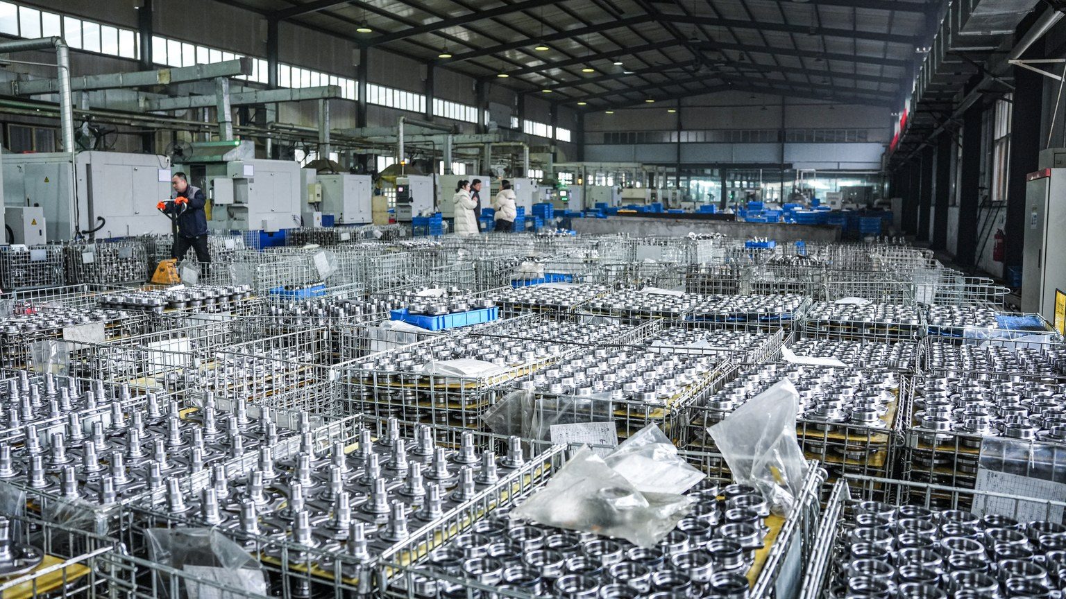
A wheel hub bearing for Ford F-150 is a sealed, pre-greased rolling bearing that carries the truck's weight at one corner and lets the wheel rotate with low friction; on most light-truck independent front axles it is supplied as a flanged hub unit that also centres the brake rotor and carries the ABS encoder ring. The correct part is not identified by the model name alone. Generation, flange and bolt-circle dimensions, bearing bore, encoder type and load rating must all be confirmed against the OE number, the drawing and a physical sample.
What Is a Wheel Hub Bearing for Ford F-150 and What Load Does It Carry?
A wheel hub bearing is the rolling element set that joins the rotating wheel to the non-rotating suspension or axle, and it performs three functions at once: it locates the wheel radially and axially, it provides the mounting face for the brake rotor and wheel, and on modern units it carries the wheel-speed encoder used by ABS and traction control.
Where the unit sits in the running gear
On an independent front suspension the hub unit is pressed or bolted into the steering knuckle, with its flange outboard and, on a driven axle, a bore through the centre for the outer CV joint stub. A rear solid axle works differently: the shaft often runs directly on a separable tapered roller bearing and cup pressed into the axle tube, lubricated by axle oil or a sealed grease pack. Because one nameplate spans many model years, drivetrains and brake packages, the same phrase can point to mechanically different parts. The governing references are the drawing and the sample, not the model year.
Which loads act on it, and why the flange follows the load
Static corner weight sets the base radial load, and road input multiplies it several times over on impacts, so the unit is sized for dynamic load rather than kerb weight. Cornering adds axial load to the angular-contact pair, which is why hub units use double-row angular contact or opposed tapered geometry instead of a single deep-groove bearing. Braking torque is reacted by the caliper bracket and the flange, not by the rolling elements, but it bends the flange root, so flange thickness and fillet radius are structural features. Wheel offset matters as well: a wheel mounted further outboard lengthens the lever arm and raises the overturning moment on the flange.
Which Hub Unit Generation Applies — Gen 1, Gen 2 or Gen 3?
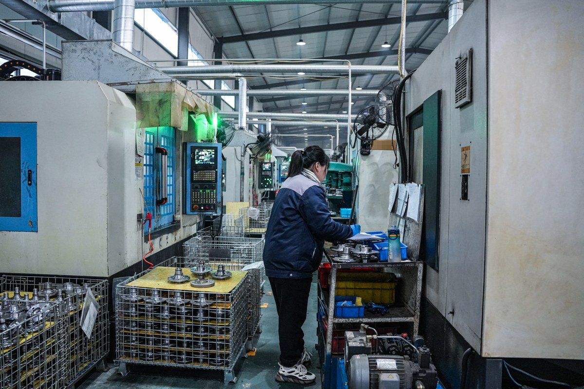
Hub unit generation describes how the bearing is mounted and what it integrates, not how advanced it is. The knuckle, spindle and brake layout decide the generation, and ordering the wrong generation is the most common sourcing error in aftermarket programmes — the difference between a wheel bearing and a hub assembly is the first thing to settle.
| Generation | Construction | What mounts to it | Typical use | Buyer check |
|---|---|---|---|---|
| Gen 1 | Double-row angular contact bearing, no flange; two inner rings retained by nut or circlip on a spindle | Raceways only; separate hub carries rotor and wheel | Older front axles, trailer and industrial shafts | Bore, width and shoulder position; end play set at installation |
| Gen 2 | Outer ring carries a flange bolted to the knuckle or axle housing; inner rings rotate | Knuckle or housing flange; separate hub for the rotor | Passenger car and light truck axles, driven and non-driven | Flange bolt pattern, pilot diameter, flange offset |
| Gen 3 | Flange on the outer ring for the knuckle plus a flange on the inner ring for wheel and rotor; sealed and greased for life | Knuckle and rotor or wheel directly | Most modern light-truck and passenger corners, including driven front axles | Encoder type, bore or spline, rotor register diameter, offset |
Tapered roller or cylindrical roller: let the load case choose
Tapered roller bearings carry combined radial and axial load in one direction and are mounted in opposed pairs, so end play is adjustable at installation; they suit rear solid axles, older spindles and positions where the shaft itself forms the inner raceway. Double-row angular contact ball bearings take lighter axial load but run with lower drag and are sealed for life, which is why they dominate Gen 2 and Gen 3 units. Cylindrical roller bearings give the highest radial capacity for a given envelope but almost no axial capacity, so they need a separate locating bearing or thrust face and appear in heavy-duty hubs rather than light-truck corner units. None of these is better in the abstract: the axle design decides.
What changes between two-wheel drive and four-wheel drive
A driven front corner needs a bore and spline that accept the outer CV joint stub and its retaining nut, and the knuckle depth usually differs from the non-driven version. Fitting a non-driven hub to a driven knuckle, or the reverse, either leaves the half-shaft unsupported or prevents it seating. Published Ford-application listings such as this front wheel hub assembly reference are useful for comparing flange, stud and spline details, but they remain catalogue entries: confirm by VIN, OE number, drawing and sample before ordering.
How Is a Hub Unit Built — Steel, Heat Treatment, Seals and Grease?
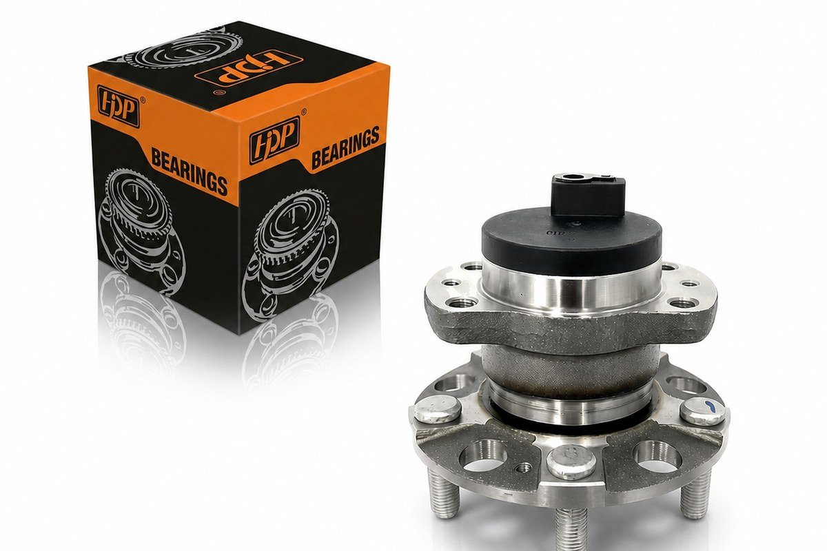
A hub unit is a system of five sub-assemblies — rings and rolling elements, flange or housing, cage, seals and grease — plus a magnetic encoder on ABS versions. Service life is set by whichever of these is specified below the duty cycle, so specifications matter more than appearance.
Bearing steel and housing material
Rings, balls and rollers are normally made from through-hardening bearing steel of the 100Cr6, GCr15 or AISI 52100 family, chosen for cleanliness and fatigue resistance rather than hardness alone. Flanges and housings use medium-carbon or micro-alloyed steel, forged or machined depending on shape and volume, and the grade belongs on the drawing because it governs yield strength at the flange root. Cage material — pressed steel, polyamide or brass — follows speed and temperature and should be stated rather than assumed.
Heat treatment and hardness windows
Through-hardened bearing rings are typically specified in the high fifties to low sixties on the Rockwell C scale, with tempering chosen so the part keeps toughness at operating temperature. Harder is not automatically better: an over-hard ring resists indentation but chips under impact from potholes and kerb strikes. Splines and flange roots are often induction hardened to resist wear while the core stays ductile. If a supplier cannot show hardness and case-depth records with the inspection report, the heat treatment is unverified regardless of what the drawing states.
Seals, grease and pre-fill
The seal, not the steel, usually ends a hub unit's life. Options run from a single lip seal to a dual lip with a metal slinger, up to a cassette seal with a separate contaminant lip, and the choice should follow the operating environment rather than the price point: fine desert dust and monsoon water demand different lip geometry and grease retention. Grease type, base oil viscosity and fill percentage belong on the drawing, because overfilling raises running torque and temperature while underfilling starves the raceway and produces early spalling. Sealed-for-life units cannot be re-greased, so the initial fill is the entire lubrication strategy.
The ABS encoder and sensor interface
On Gen 2 and Gen 3 units the wheel-speed signal comes from a magnetic encoder ring bonded to the seal or inner ring and read by a sensor mounted in the knuckle. The ring is magnetised in alternating poles and the sensor counts pole transitions, so pole count, magnetisation pattern and air gap must match the vehicle's control unit. A hub unit that is dimensionally correct but carries the wrong encoder produces a wheel-speed fault with no mechanical symptom at all. The OE number and ABS fitment checks that apply to any hub unit apply here unchanged.
Which Drawing Parameters Decide Whether the Part Fits?
Fit is decided by a short list of dimensions and material callouts. If any of them is missing from the drawing, the part is not yet sourceable, no matter how complete the catalogue photograph looks — the hub and bearing selection guide sets out the same order of checks.
| Parameter | Usually given as | Why it decides fit |
|---|---|---|
| Pilot diameter and flange face | mm with tolerance | Centres the rotor and wheel; an undersized pilot causes runout and vibration |
| Bolt circle and hole count | Pitch circle diameter, hole size, thread | Wheel and rotor attachment; a wrong pitch circle cannot be corrected on fitting |
| Flange offset and overall height | mm from mounting face | Sets the rotor plane and caliper clearance |
| Bore or spline | mm, spline data, retaining feature | Half-shaft engagement on driven axles |
| Outer ring diameter and width | mm with tolerance class | Press fit in the knuckle; interference controls creep and fretting |
| Encoder type and pole count | Active or passive, poles per revolution | ABS and traction-control signal compatibility |
| Internal clearance or preload | Clearance group or preload value | Noise, heat generation and fatigue life |
| Material and heat treatment | Steel grade, hardness, case depth | Load capacity and impact resistance |
Clearance groups: what the code means
Internal clearance is the total movement available between rings before load is applied. Catalogues express it in groups — C2 reduced, CN normal, C3 and C4 increased — and the group must suit the fits, the temperature difference between inner and outer ring and the speed. In sealed hub units clearance is fixed at assembly, so it is a design output rather than an installation adjustment. In opposed tapered pairs it is set on the vehicle by nut torque or by measuring end play, and both extremes damage the part: too little clearance generates heat and can seize the bearing, too much produces noise, runout and shorter fatigue life.
Who develops the part from a drawing
Jinan Huayuan Bearing Co., Ltd., publishing as huayuanbearing.com from Jinan in Shandong, manufactures and exports wheel hub bearings, hub units, tensioner pulleys and CV joints for aftermarket replacement and assembly supply, mainly to customers in the Middle East and Southeast Asia. The company develops parts to a customer drawing or a physical sample and supports custom packaging and private-label marking, so the parameters above are the ones to agree before a sample is built. A rear corner can diverge just as sharply from the front: this rear wheel hub assembly listing shows how flange height and mounting detail change between positions.
How Do You Diagnose a Failing Hub Bearing Before Replacing It?
A failing hub bearing usually shows one of three symptoms — speed-related noise, measurable play, or an ABS warning — and the combination identifies whether the bearing, the CV joint or the sensor circuit is at fault. Diagnosis should end with a measurement, not an opinion; the practical sequence in how to tell a wheel hub bearing is failing follows the same logic.
- Road test and record the conditions. Note the speed band where noise appears, whether it changes when steering left or right, and whether it disappears under braking.
- Load each side in turn. A steady swerve transfers weight across the axle; a hub bearing normally gets louder when the suspect side is loaded and quieter when it is unloaded.
- Raise the corner and spin the wheel. Listen at the hub with a stethoscope or a screwdriver handle, and feel for rough or notchy rotation.
- Check play in two planes. Rock the wheel at twelve and six o'clock, then at three and nine; play in both planes points to the bearing, play in one plane may point to a suspension joint.
- Inspect the seal area. Grease weeping, rust streaks or a displaced seal indicate water or grit ingress and a bearing that is already degrading.
- Read the brake and tyre evidence. Uneven pad wear, a scored rotor or a cupped tyre can imitate bearing noise, so rule them out before ordering.
- Check the ABS data. Compare wheel speeds on a road test; a divergent signal with no mechanical play points to the encoder ring or the sensor air gap.
Which symptom points where
A hum or whine that rises with road speed and shifts with steering load is characteristic of a hub bearing. A single sharp click repeated on tight low-speed turns belongs to a worn outer CV joint. Grinding that appears only when the brakes are applied comes from pads, rotors or a bent backing plate. An ABS lamp combined with vertical play indicates encoder damage caused by bearing movement, in which case replacing the sensor alone will not clear the fault.
What Should You Check at Installation and Incoming Inspection?
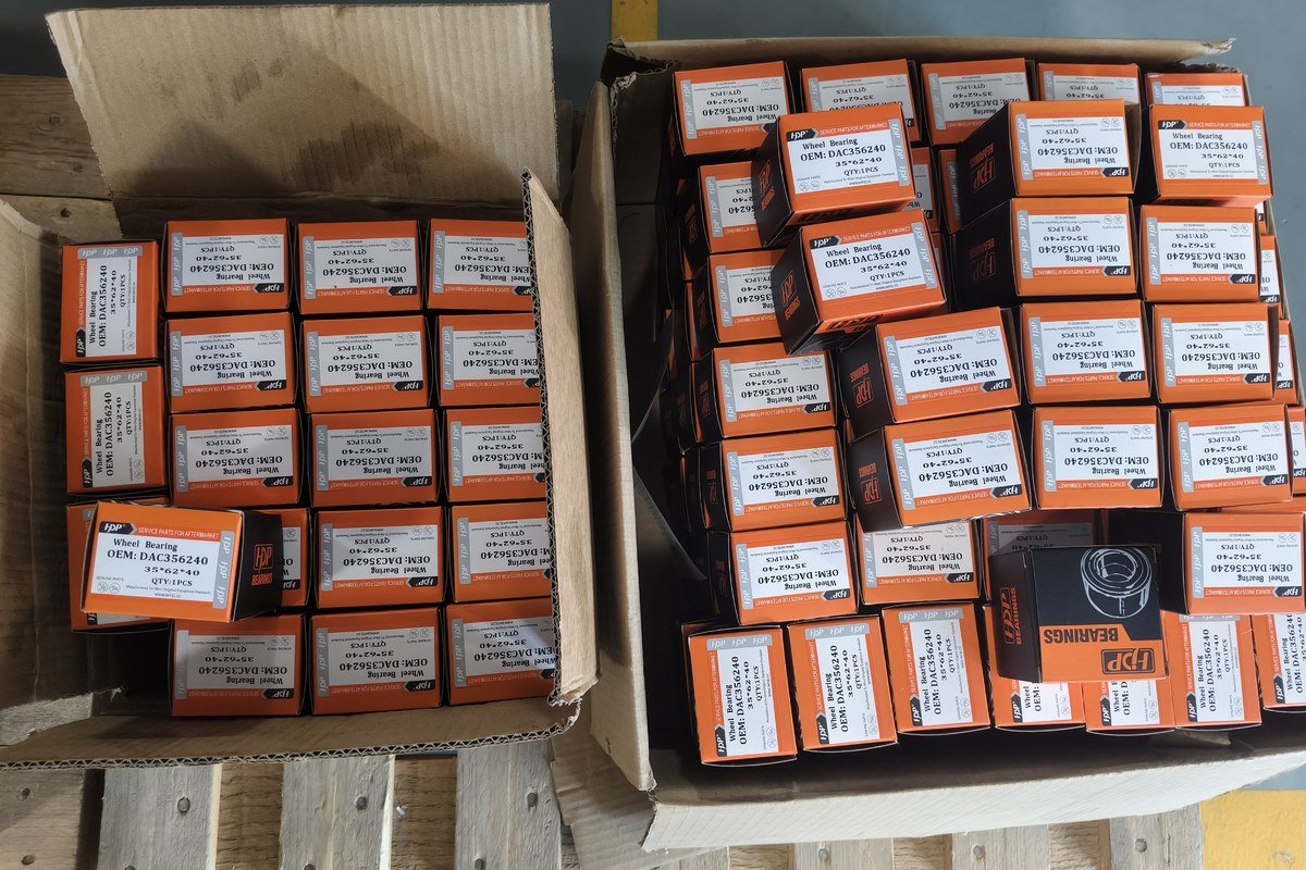
Most premature hub unit failures are installation errors rather than manufacturing defects: contamination during fitting, press force transmitted through the balls, a reused axle nut, or a knuckle bore left with corrosion and burrs. The hub bearing RFQ checklist covers the purchasing side of the same points.
Installation sequence
- Verify the new unit against the OE number, the drawing and the removed part — measure, do not eyeball.
- Clean the knuckle bore and mounting face; remove corrosion, old thread-locking compound and brake dust.
- Check the bore for roundness, scoring and burrs, because a distorted bore transfers its shape to the outer ring.
- Apply press force to the outer ring or flange housing only, never to the flange face or through the rolling elements.
- Support the inner ring when pressing a shaft or CV stub into the hub, so the load path does not cross the raceways.
- Fit new fasteners where the vehicle maker specifies single-use bolts or nuts, and torque to the published figure rather than a generic value.
- Check rotor runout and confirm the sensor air gap with a feeler gauge before refitting the wheel.
- Road test, then re-check for play and abnormal hub temperature after the first journey.
Incoming inspection for importers and distributors
| Check | Method | Reject if |
|---|---|---|
| Packaging and marking | Compare with approved artwork | Wrong private-label print, missing lot code |
| Boundary dimensions | Micrometer and caliper against drawing | Any dimension outside tolerance |
| Flange flatness and runout | Dial gauge on a surface plate | Runout above the drawing limit |
| Rotation quality | Hand spin, then torque meter | Rough feel, tight spot, audible growl |
| Seal and grease | Visual check and glove wipe | Displaced seal, grease on the flange face |
| Encoder | Compare against a reference sample | Missing ring, wrong pole pattern, damaged surface |
How Do Tensioner Pulleys and CV Joints Compare in Structure and Duty?
Tensioner pulleys and CV joints sit in the same running-gear family as hub units but fail for entirely different reasons, so a mixed container should be inspected against different criteria for each product type.
Tensioner pulley: bearing, arm and spring
A tensioner assembly combines a sealed deep-groove ball bearing with a stamped or polymer pulley on an offset arm loaded by a coil or torsion spring, often with a damping element to control belt flap. The bearing is the wear item: grease loss shows as dust around the seal, and the first symptom is usually a chirp at idle that disappears with engine speed. Pulley squareness to the belt run and spring condition matter as much as spinning the bearing by hand.
CV joint: races, cage, balls and boot
A fixed outer joint of the Rzeppa type uses an inner race, a cage, six balls and an outer race; a plunging inner joint of the tripod type uses three rollers on trunnions running inside a housing. Both depend on the boot: once it splits, grease is thrown out and abrasive grit enters, and the joint fails soon afterwards. Boot condition is therefore the primary inspection point on a used joint, and boot material and clamp quality are the specification items worth controlling on new parts.
Frequently Asked Questions
Does a wheel hub bearing for Ford F-150 come as a bare bearing or a complete assembly?
Both formats exist across model years and drivetrains. Many light-truck front corners use a complete hub unit with flange, studs and encoder, while rear solid axles often use a separable tapered roller bearing and cup running directly on the shaft. The axle design decides it, and the removed part or the OE number confirms it. Treat the drawing and a physical sample as the final reference.
How can I confirm the right hub unit without trusting a model-year list?
Use four checks in order: the OE number from the vehicle or the old part, boundary dimensions from the drawing, interface details such as pilot diameter, bolt circle, spline and encoder, then a direct comparison with a sample. A model-year list is an index, not evidence. huayuanbearing.com reviews hub bearing enquiries against the drawing and sample rather than the model name.
Can a worn hub bearing trigger an ABS or traction-control warning?
Yes. Gen 2 and Gen 3 hub units carry the magnetic encoder ring that the wheel-speed sensor reads. Bearing play, a damaged seal, metallic debris or a corroded ring distorts the signal, so the control unit logs a wheel-speed fault before the bearing becomes audible. Check play and the encoder surface before replacing a sensor.
Should hub bearings be replaced on both sides at once?
Not automatically, but often sensibly. Both sides of an axle see the same duty cycle and usually the same mileage, so when one side shows play the other is often close behind. On a high-mileage vehicle, replacing both sides reduces repeat labour and the risk of a second failure shortly after the first repair.
Purchasing guidance, product information and company updates from Huayuan Bearing.